|
|
|
|
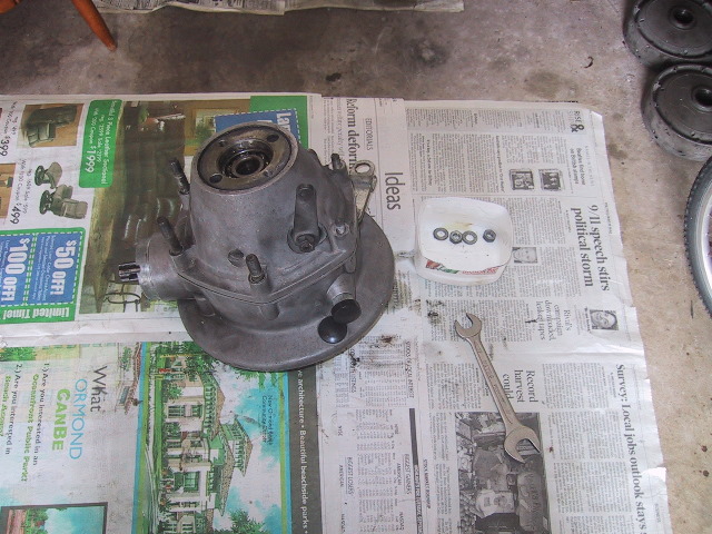
Final Drive Disassembly With 2wd
Note: This DOES NOT cover the "Sportsman" final drive (pre-2000)
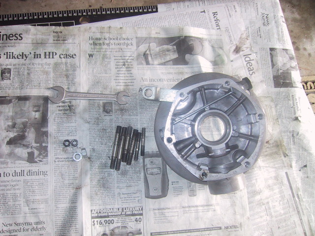
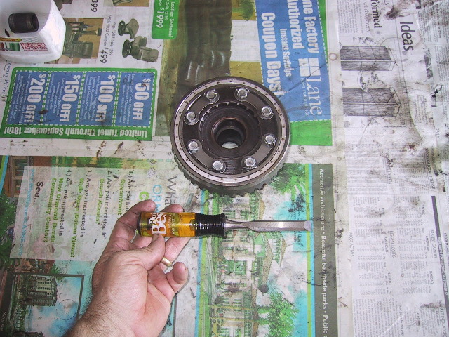
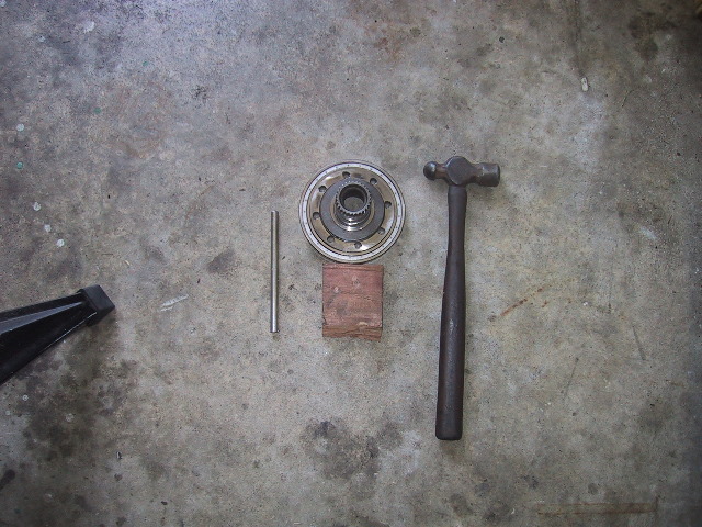
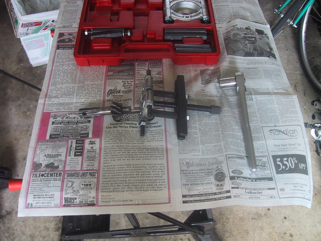
Tools Needed: 13mm, 17mm wrench, axle, URAL pin spanner, magnetic pick-up, long shank thin blade screw driver, hammer, tommy bar, 19mm socket, 6" extension or longer, 3/4" tip wood chisel, 12mm socket and ratchet, wood blocks, vise and 2" bearing separator.
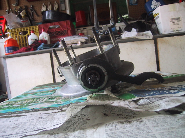
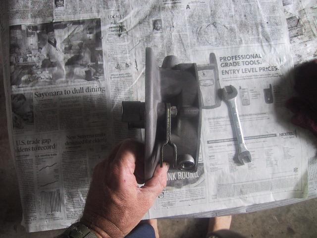
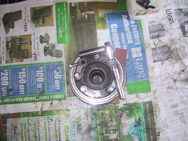
7.6(a): Separating the Outer Case from the Final Drive Case
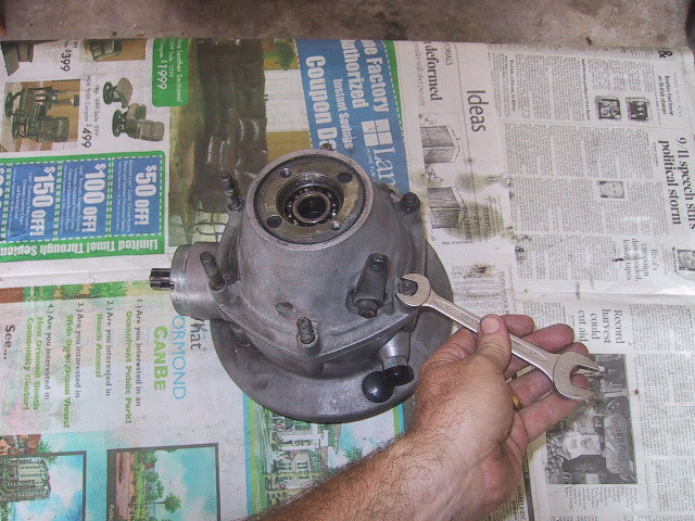 Use A 13mm open end wrench to remove the two nuts holding the outer cover to the final drive case.
|
Put all the bits & pieces in containers so they don't get lost. I use cut down oil bottles as parts bins. |
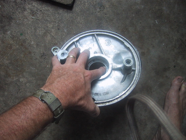
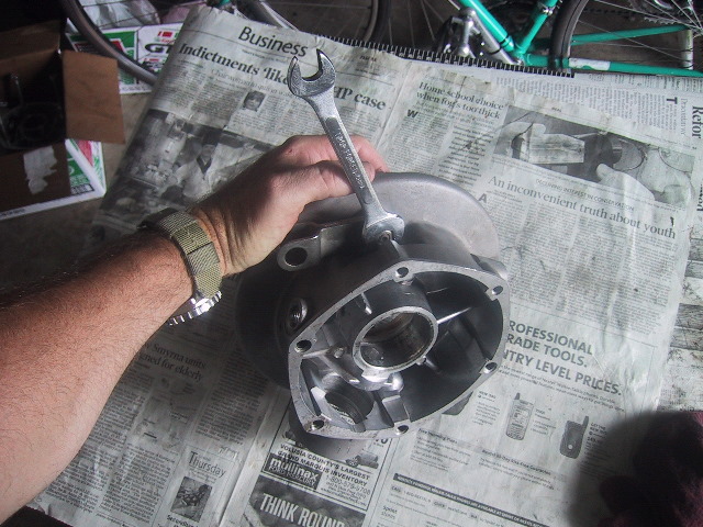
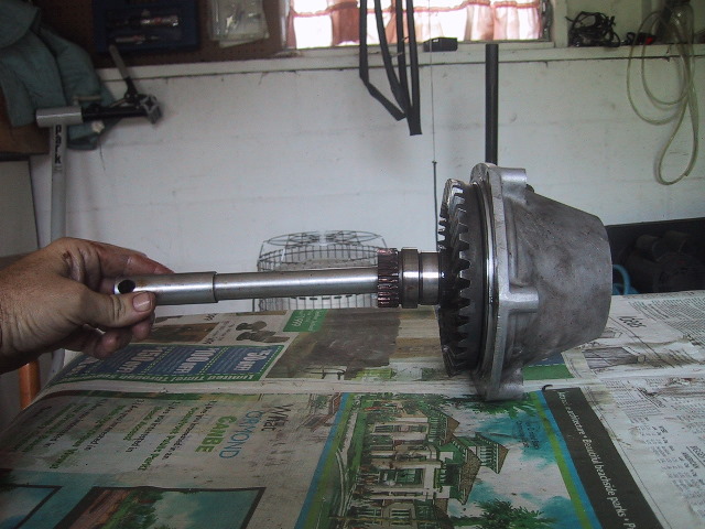
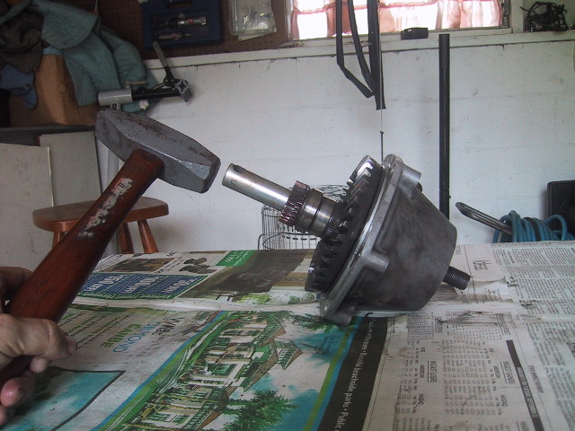
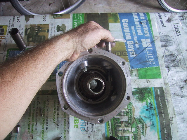
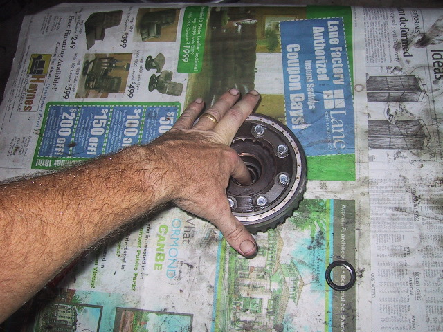
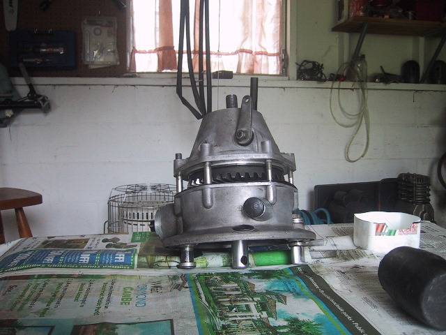 Slip the rear axle up through the final drive and bump the f.d. on a table or rap it gently with a hammer to separate the outer case (top) from the final drive case (bottom). |
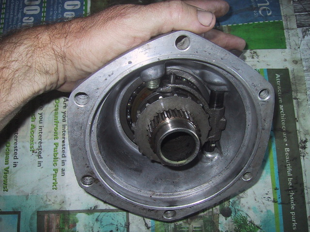
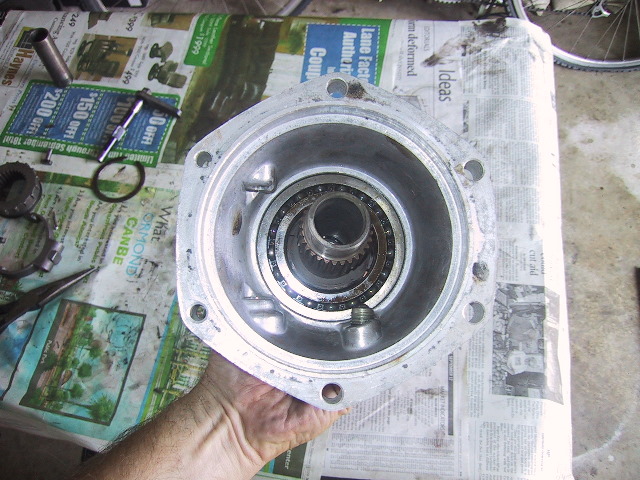
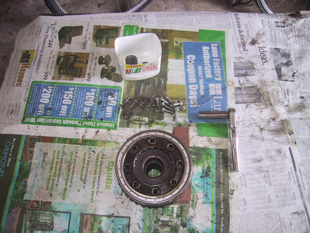
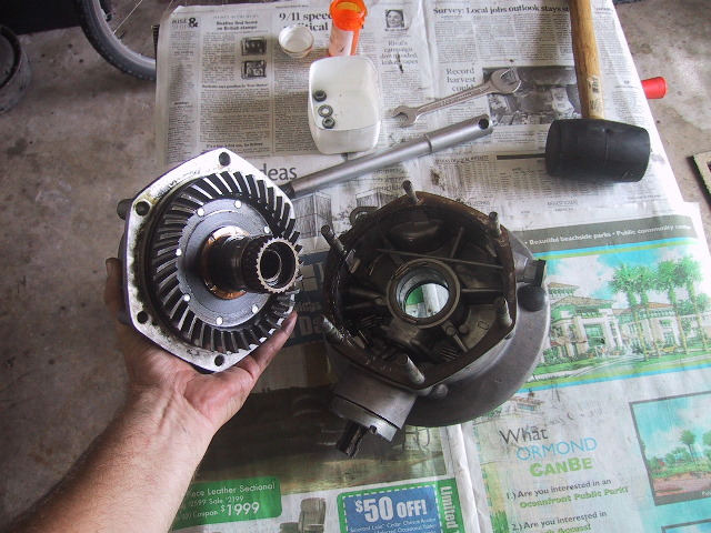 Remove the outer cover which contains the ring gear/driven gear hub which is what the wheel drum splines mount to. Set the outer cover assembly aside. Be careful as some of the 45 needle bearings stuck in the grease on the driven gear might fall off. |
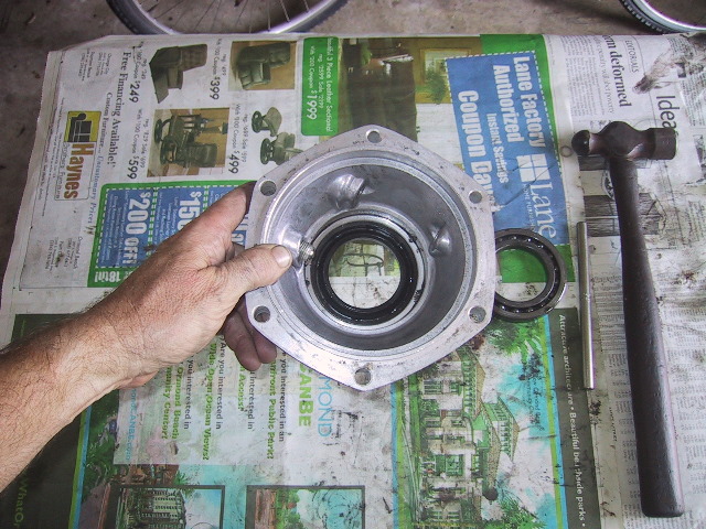
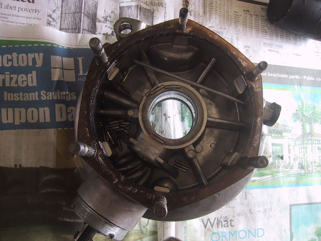 The final drive case will have one or more paper gaskets installed. Make note of how many are used. The gaskets act as spacers to obtain the proper clearance between the ring and pinion gears. Note the needle bearings laying inside. |
 The needle bearings ride here on the driven gear hub. |
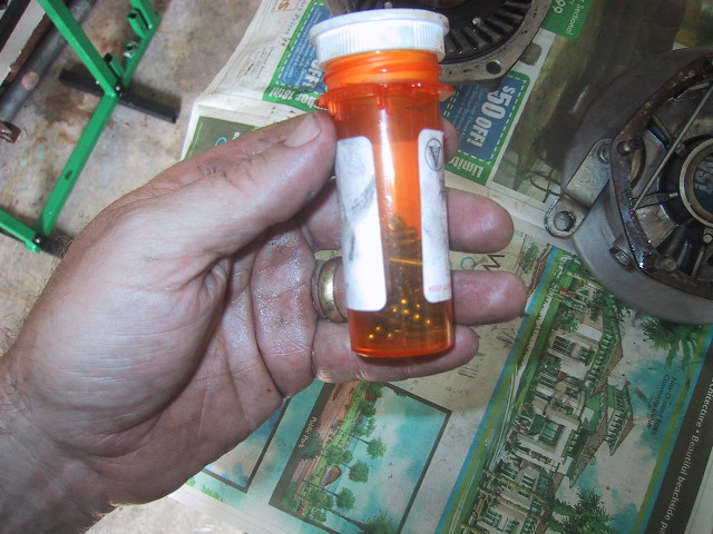 I use old pill bottles to hold the tiny bits... |
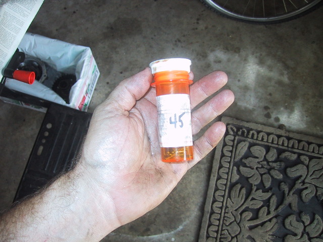 ...and label them for later identification. |
 Put the outer cover and bearings aside as we will continue to tear down the final drive housing. |
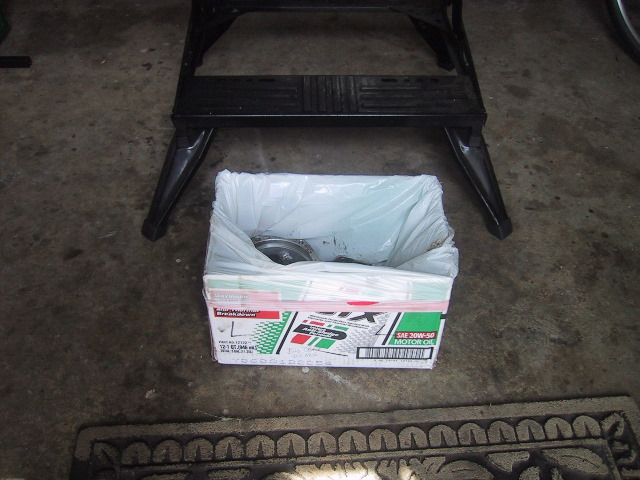
I use cardboard boxes from a case of oil and kitchen garbage can bags to make parts holders. You can pad the bottoms with newspaper. |
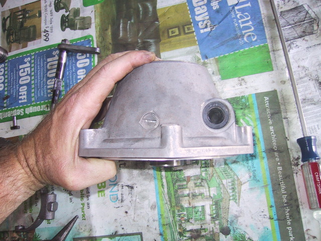
7.6(b): Final Case Disassembly
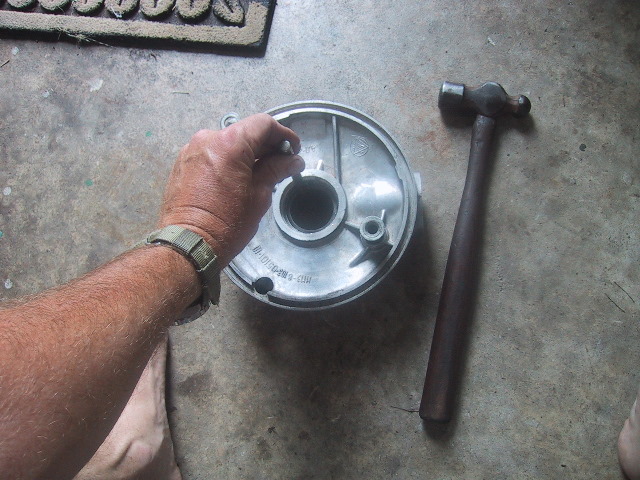
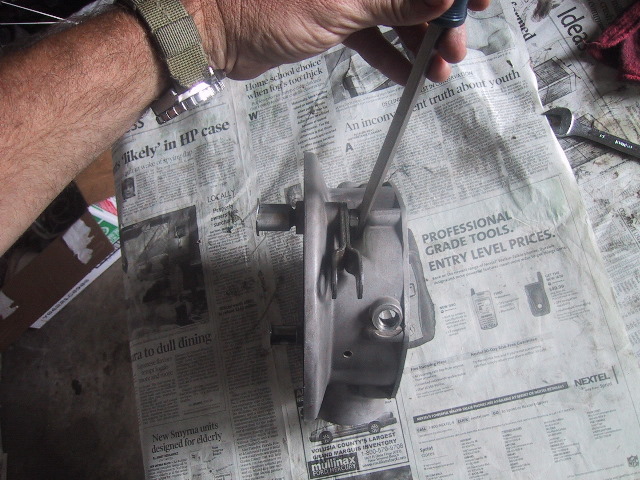
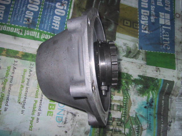
 Continuing with the disassembly of the final drive housing... you can see the final drive dip stick on the left, the drain plug at 7 o'clock and the top paper gasket. |
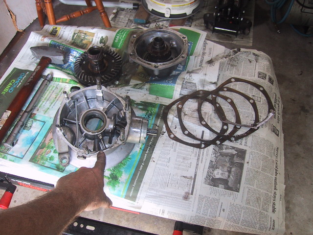 This particular final drive used 4 paper gaskets. The gaskets are used as shims to set the ring gear/pinion gear lash.
|
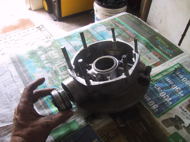
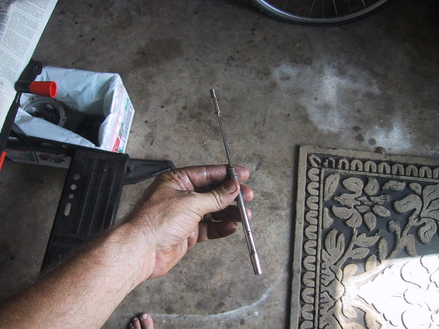
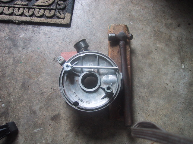
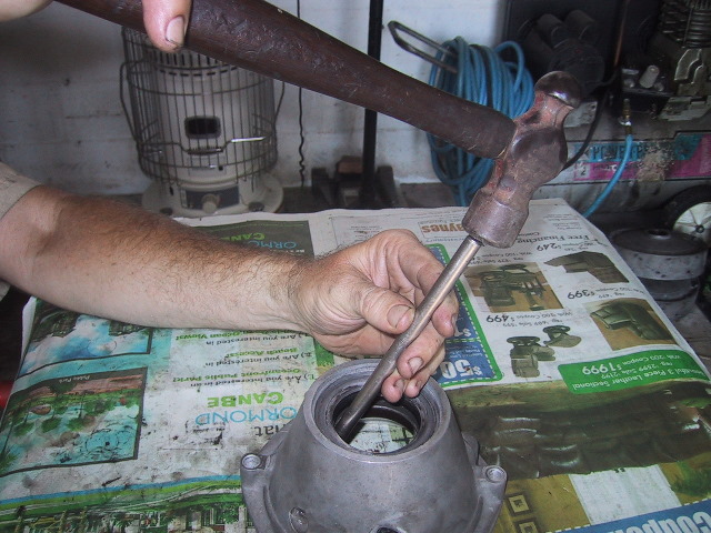
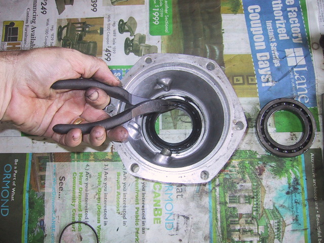
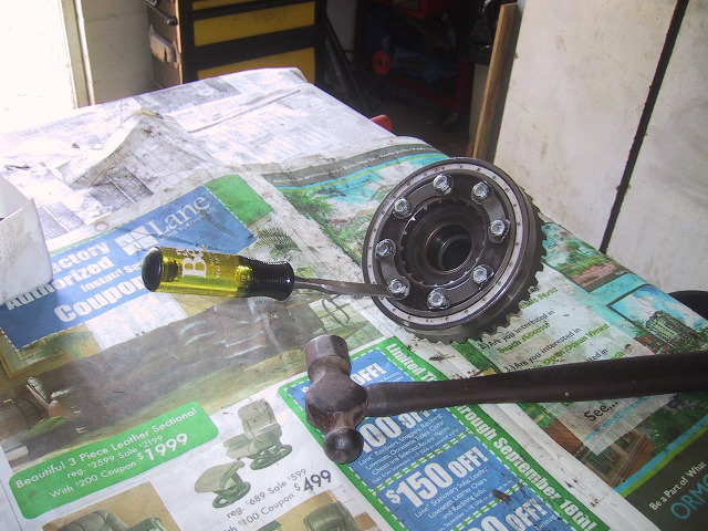
 Use the single tooth pin spanner from the URAL tool kit to remove the bearing nut and seal.
|
 It is a left hand thread so CW to loosen!
|
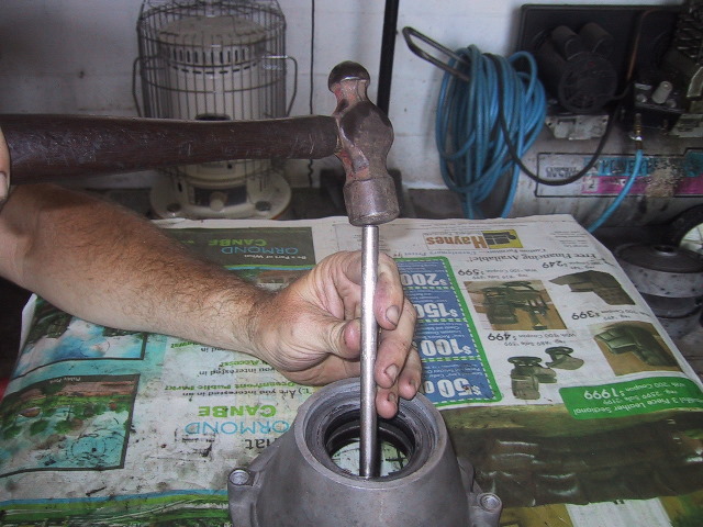
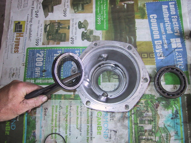
 Turn the bearing nut off and remove...
|
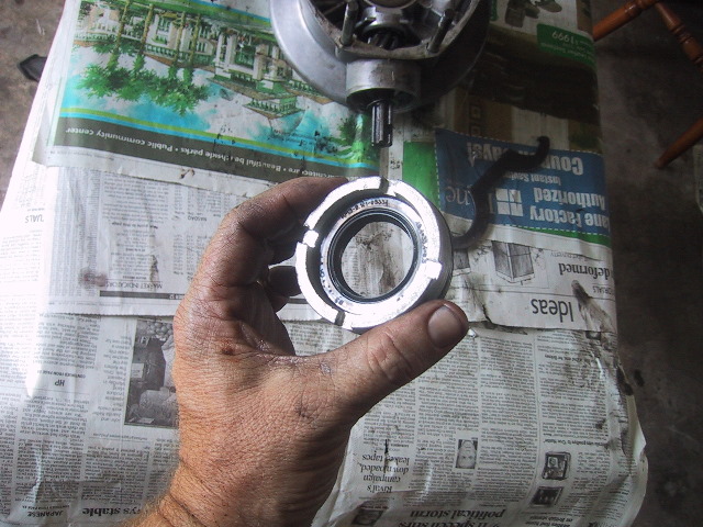 ...note the seal is 33X49.4X8 which is "fractional mm's" and only available through your URAL dealer.
|
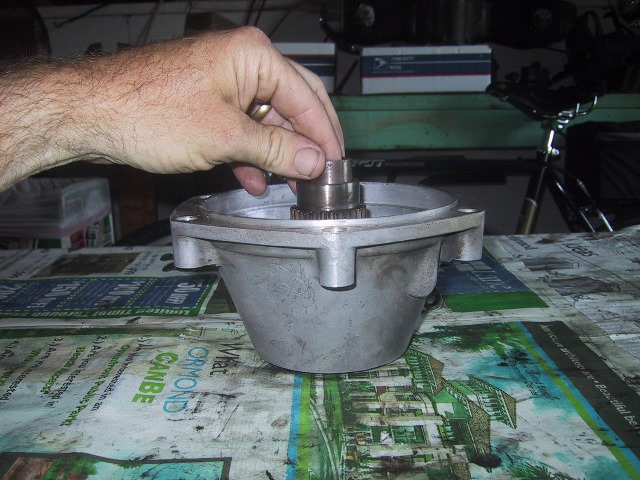
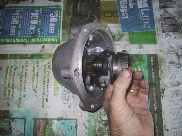
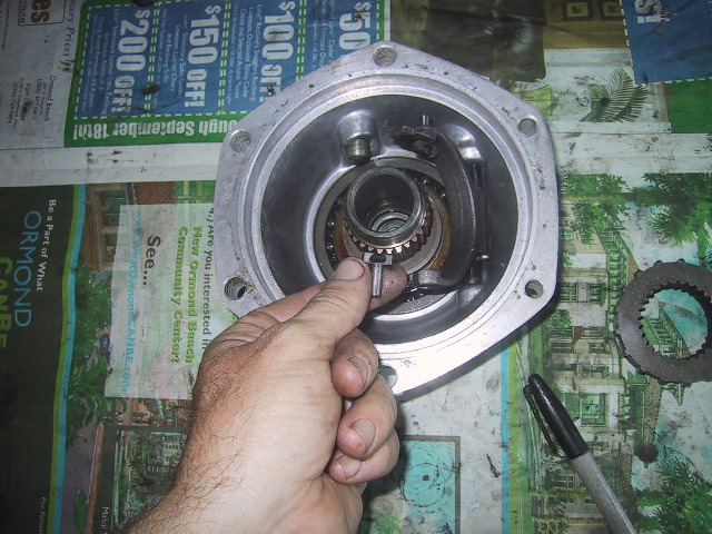
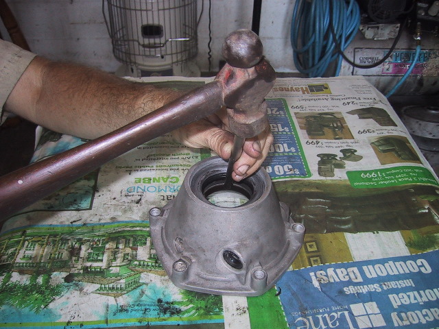
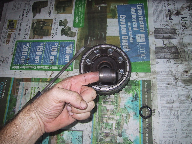
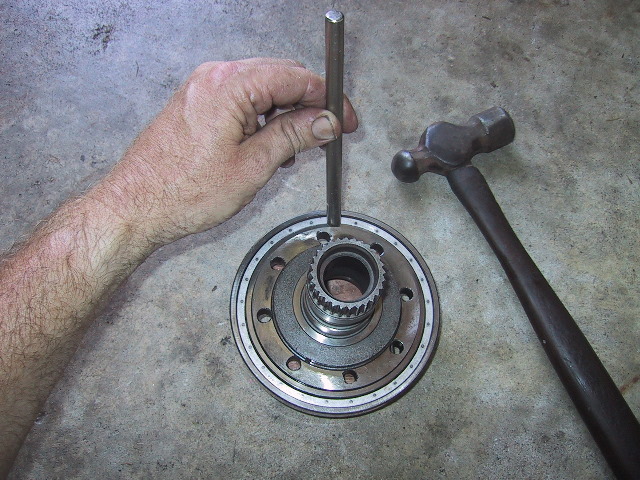
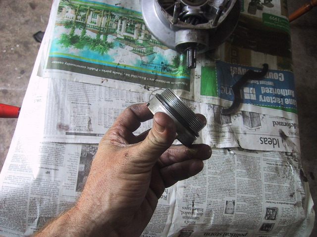 You should replace the O-ring seal while the bearing nut is off. Note the splined shaft on the pinion gear is now exposed.
|
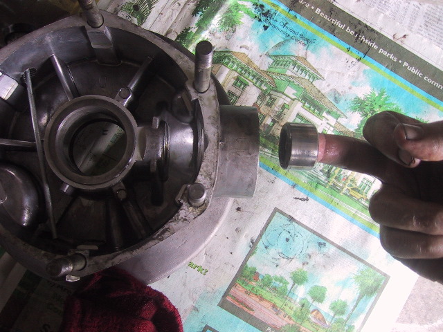
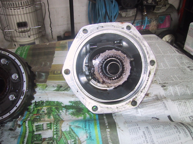
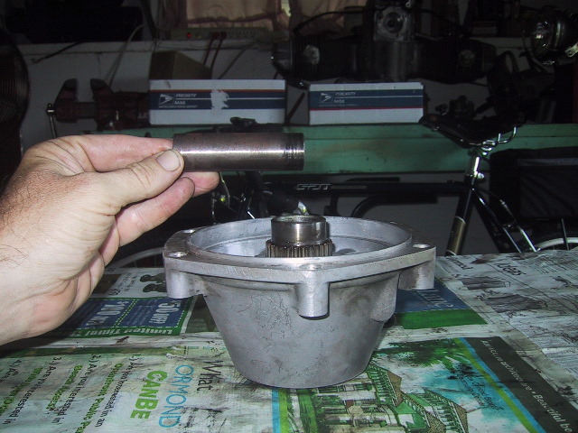
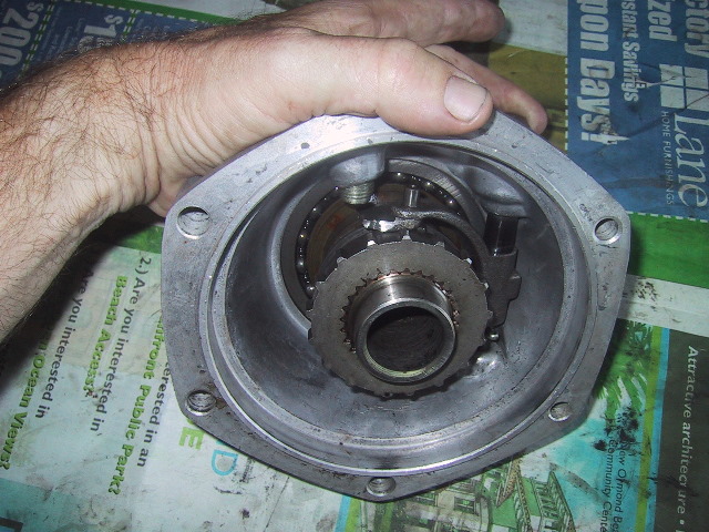
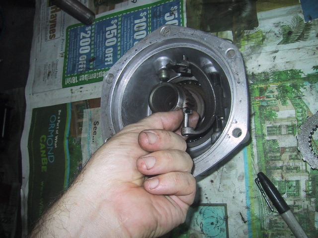
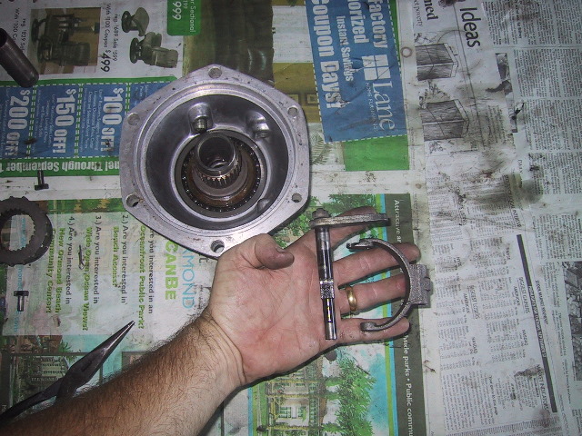
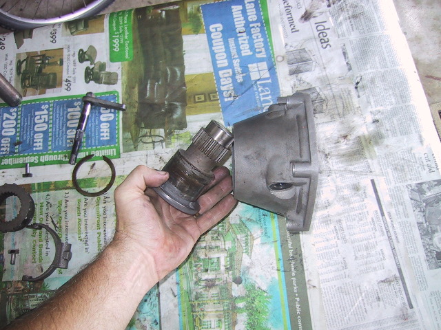
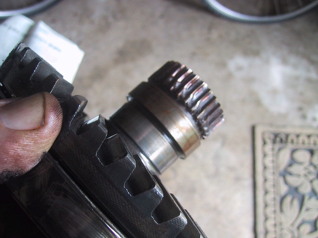
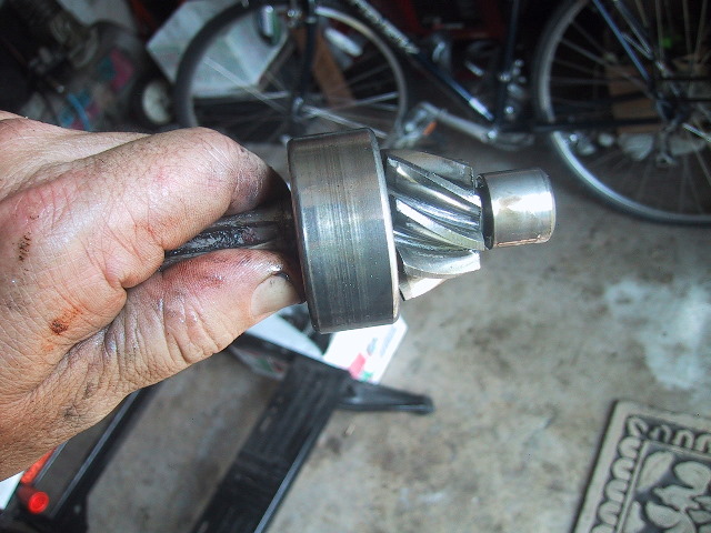
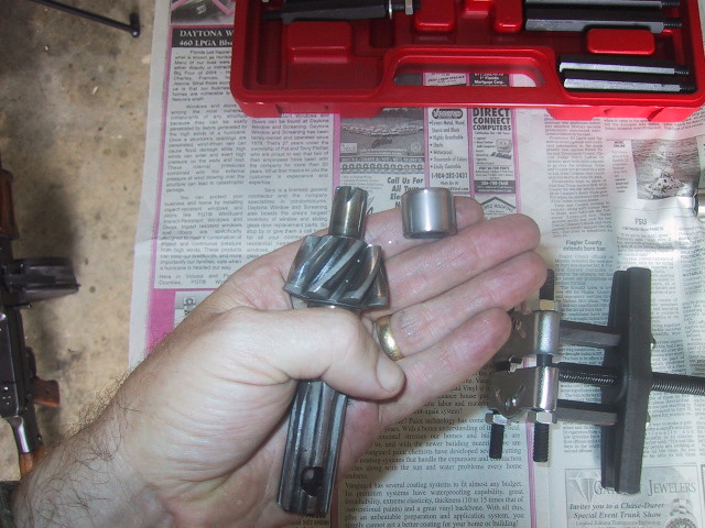
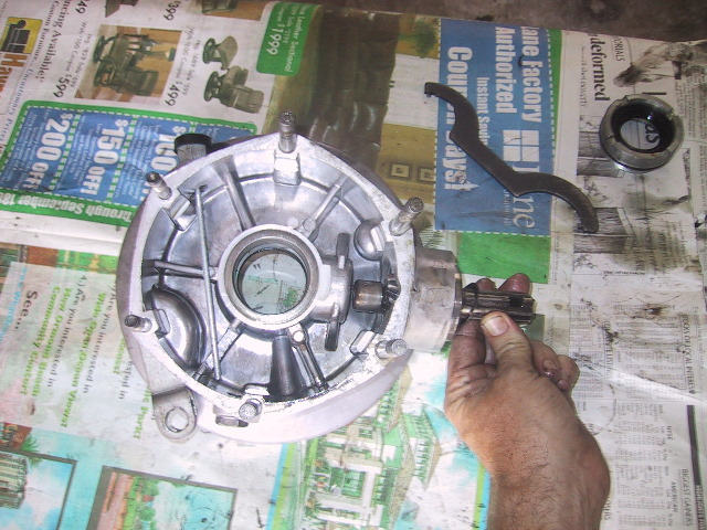 Grasp the pinion gear shaft and pull it free. Careful as there are 28 needle bearings riding on the tip of the pinion gear. Some may come out with the gear. |
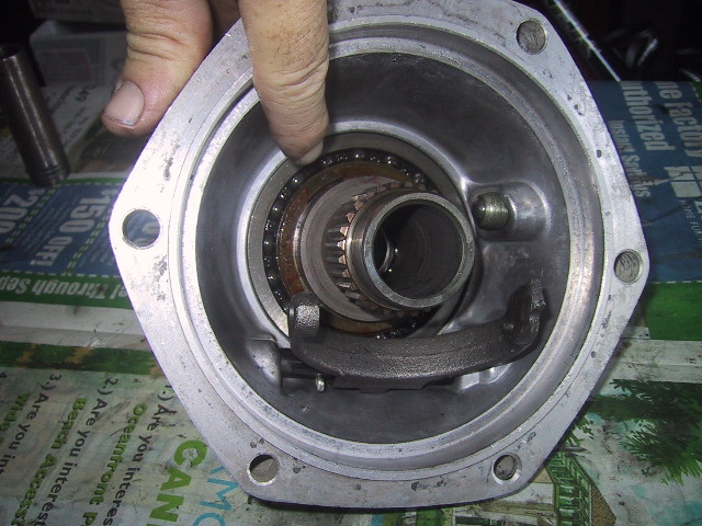
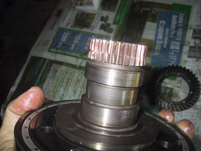
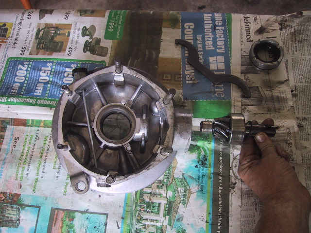 A gentle tug and the pinion gear is free. The inside race of the needle bearing is now plainly visible. The outer race and needle bearings are still in the final drive housing. |
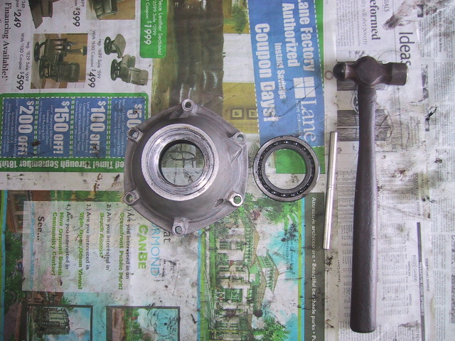
 Inner needle bearing race...
|
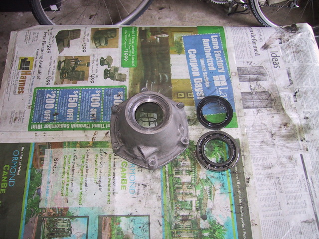
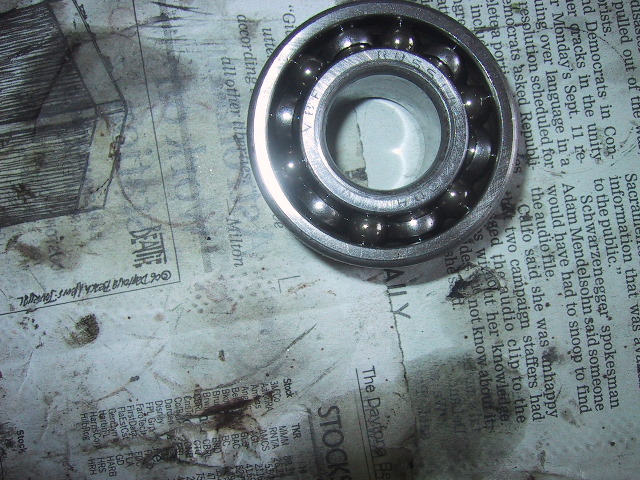
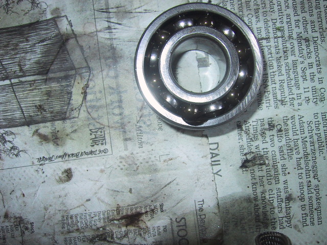
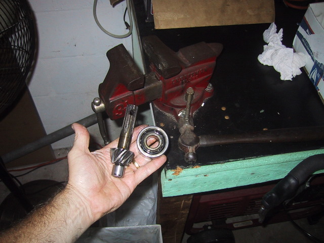
 ...#5304 double row roller bearing...
|
 ...and adjustment shims for pinion the to ring gear lash. Remember to look for these stuck to the back of the drive shaft U-joint when removing it.
|
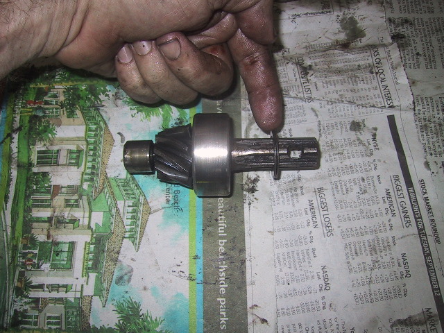
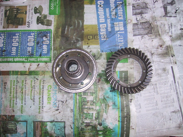
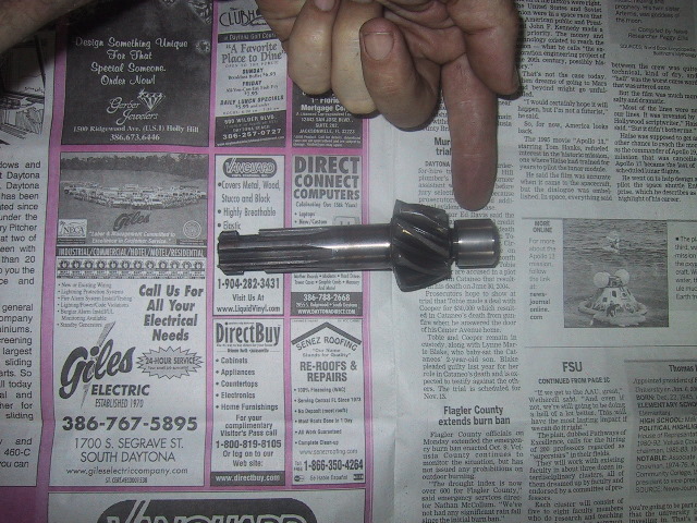
 This is how the pinion gear runs on the ring gear. Place the pinion gear in the parts box as we will finish taking it apart later.
|
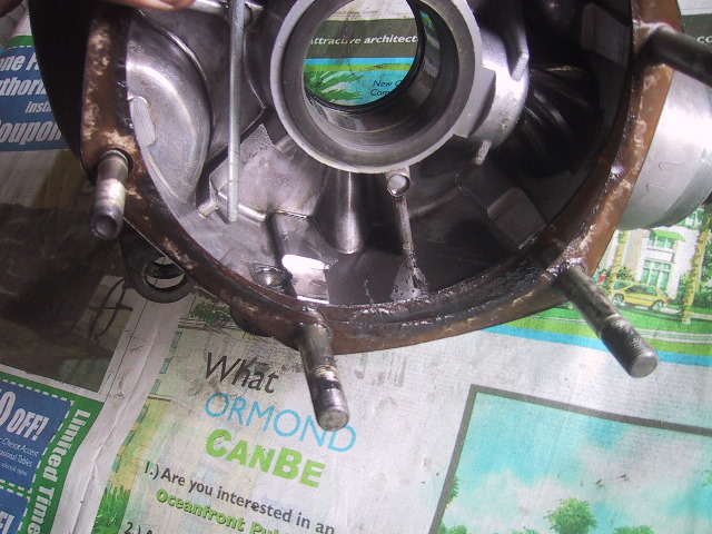
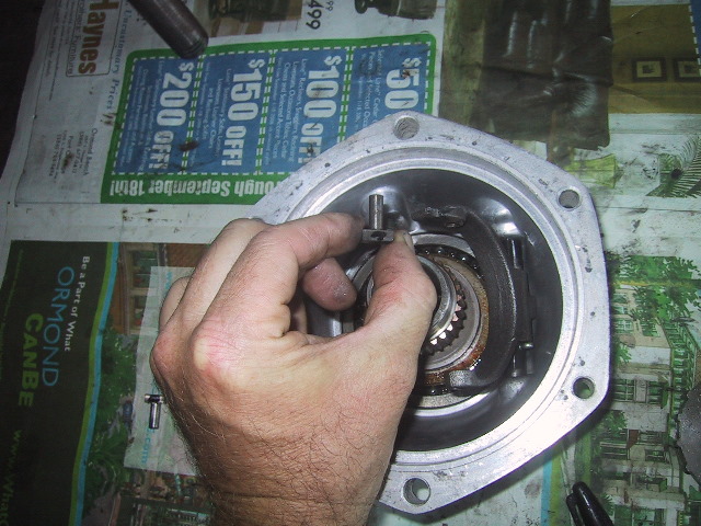
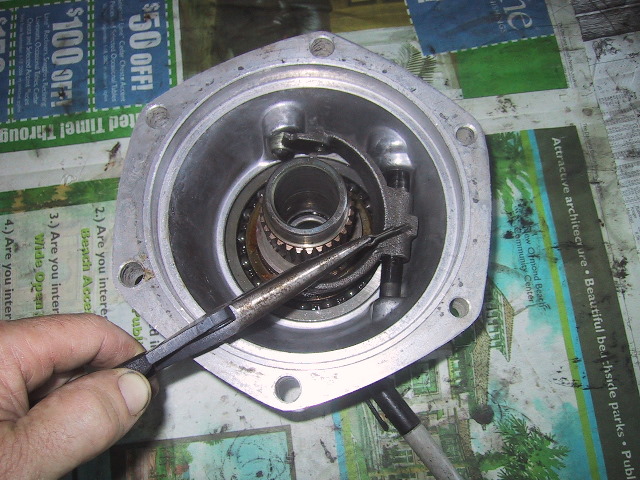
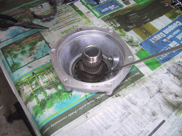
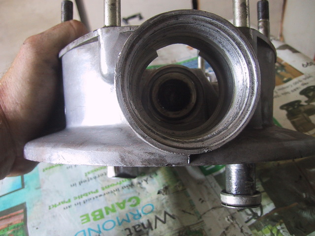 Not a good view...but you can see the outer needle bearing race...trust me, there are 28 needle bearings stuck in the grease down there... |
 ...another bad picture trying to show the needle bearings.
|
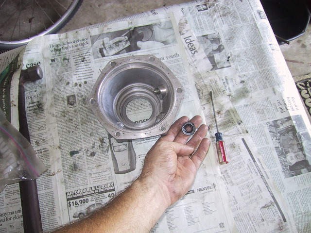
 I use one of those expandable magnetic pick-ups to reach in and collect the loose needle bearings...
|
 ...just like fishing!
|
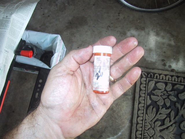 Again, I use a pill bottle to label and store the bearings.
|
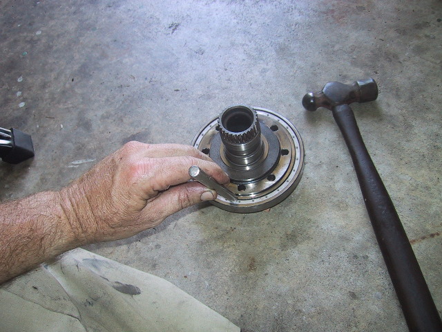
 If you have a lot of km's on your final drive...you can probably just reach in a pull the outer needle bearing race free (not good). If not, you will need a pilot bearing puller or use a long bolt with a washer and nut inside the lip of the outer race and yank it out. |
 This needle bearing is an odd-ball bearing and not available aftermarket. You will need to acquire one through your nearest URAL dealer
|
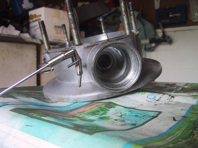
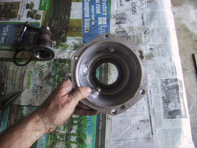
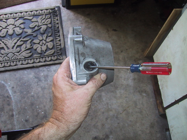
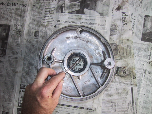 Turn the final drive housing over and use a long flat blade screwdriver...
|
 ...to remove the 45X59X7 final drive housing collar seal.
|
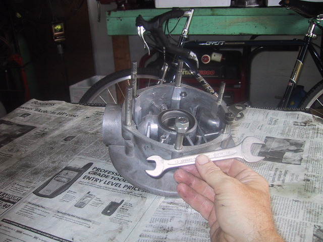 Using a 13mm X 17mm wrench, double nut the 13mm and 17mm final drive studs...
|
 ...and remove them. You only need to do this if you are replacing/repairing or stripping a trashed housing. |
 If necessary, the steel hub insert can be removed...
|
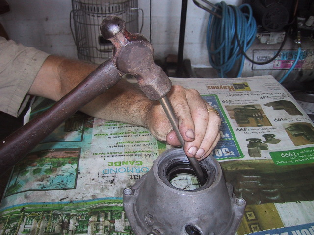
 ...by placing the final drive on some wood blocks and use the tommy bar and hammer...
|
 ...to tap it out. Again, not necessary under normal conditions.
|
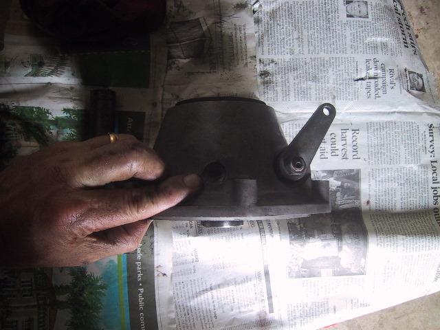
 To remove the rear foot brake linkage and cam...
|
 ...use a 13mm wrench to remove the nut...
|
 ...and a flat blade screw driver to push the splined rod through the housing.
|
 The forward brake cam is a press fit and must be heated and pulled to remove which can damaged it. I just left it in.
|
Put the disassembled final drive housing components in the parts box and pull out the final drive outer cover for further disassembly. |
7.6(c): Outer Case Disassembly
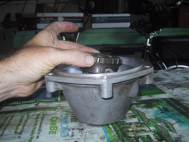
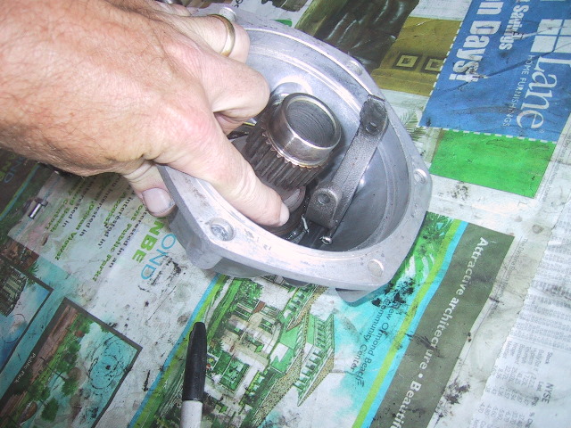
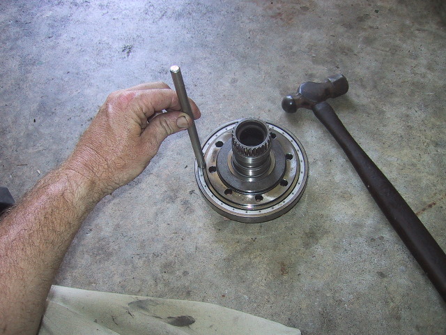
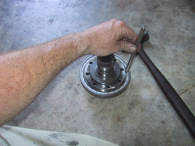
 To separate the driven gear hub from the outer cover...insert an axle from the inside of the outer cover housing... |
 ...and tap it several times to... |
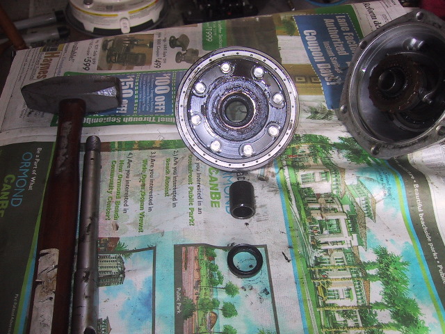
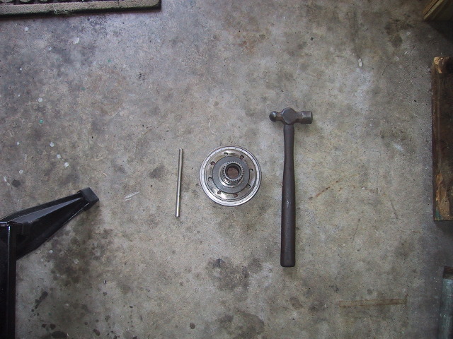
 ...separate the components. Occasionally the large 140mm bearing will remain in the outer housing. It can be removed with a long punch. |
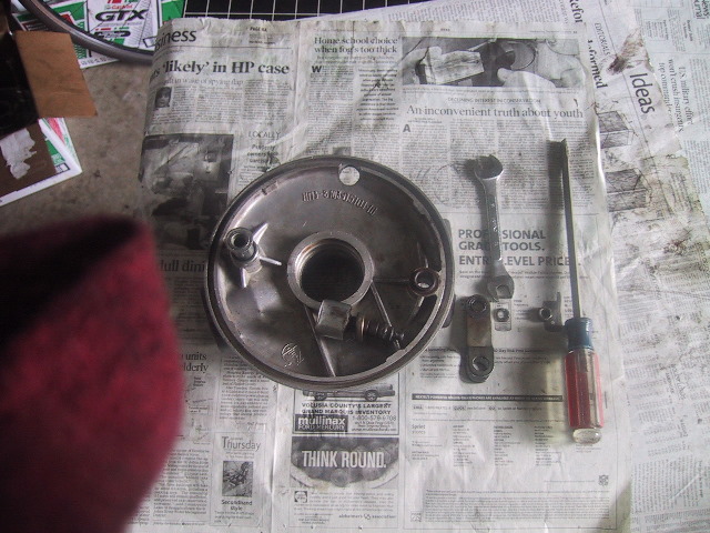
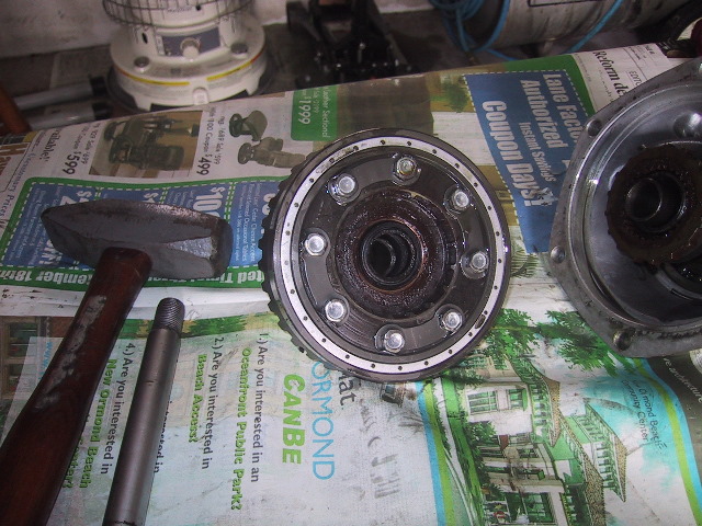 Head on view of the driven gear hub. |
 Inside of the outer cover showing the 2wd shift coupling gear. |
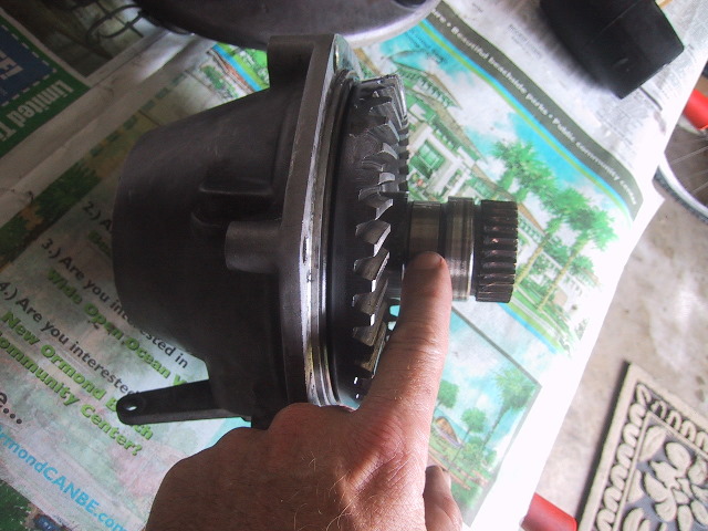
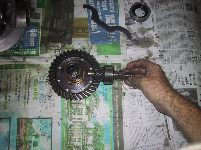
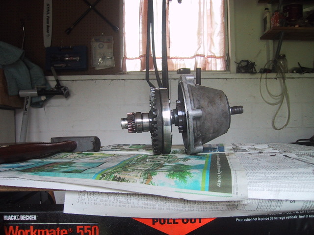
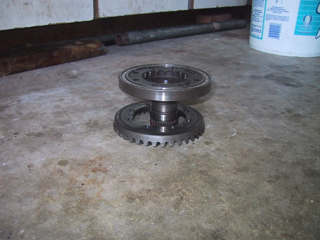
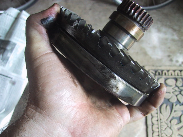 A profile view of the driven gear hub, pinion gear and large drive bearing. Note the worn teeth on the driven hub splines. These mesh with the wheel hub splines. |
Place the driven gear hub in the parts box and we'll continue tearing down the final drive outer cover. |
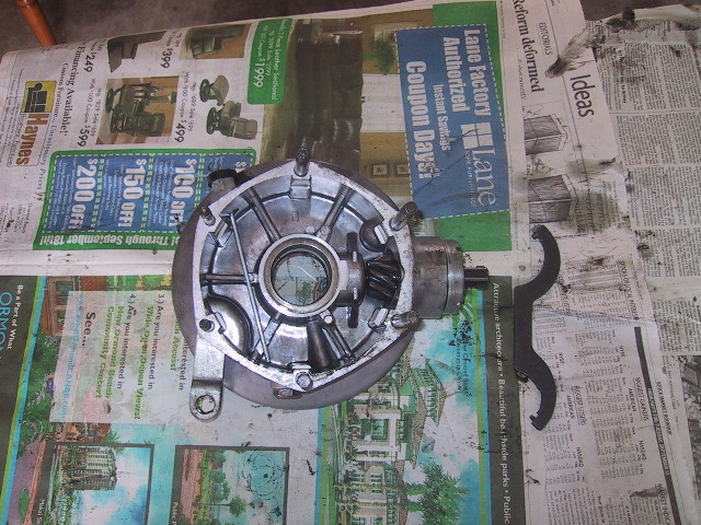
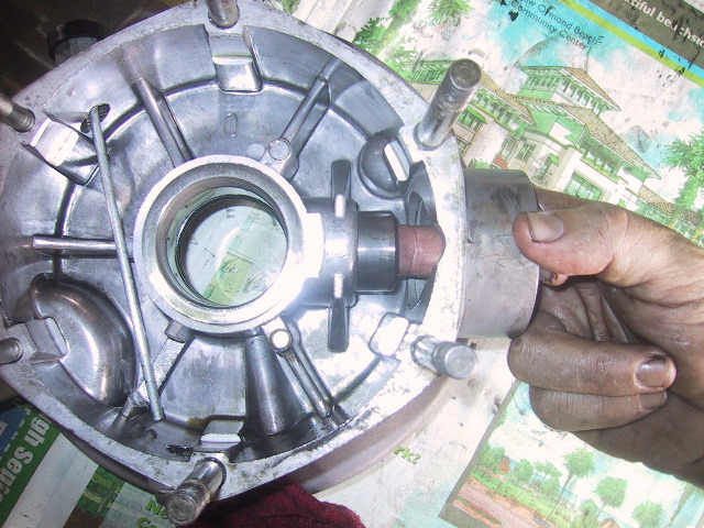
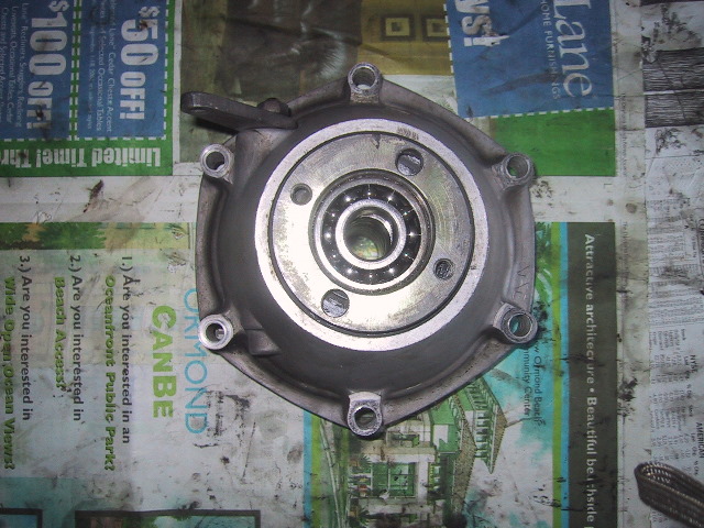 Top view of the outer cover. You can see the #204 bearing in the middle. The bearing is inside the splined hub. |
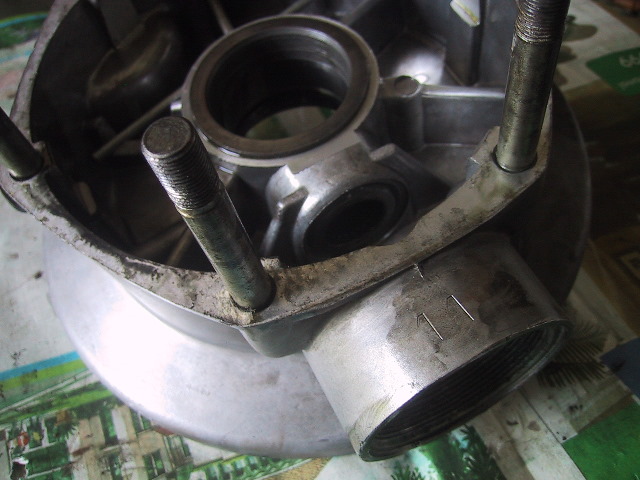
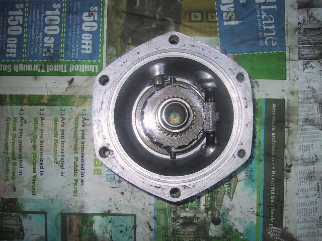 Inside view of the outer cover. At 11 o'clock the locking detent for the 2wd lever is visible. The 2wd shift coupling gear is in the center and to the right the vertical shaft of the engagement lever with the sliding fork for the gear is just visible. |
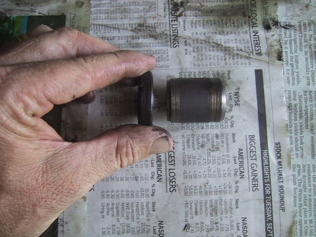
 If it hasn't fallen out already, remove the tube spacer...
|
 ...from the outer cover. |
 Here is the 2wd locking detent screw. |
 You need a very large screw driver to remove it. Mine would not come out. It is not necessary to remove it for further disassembly. |
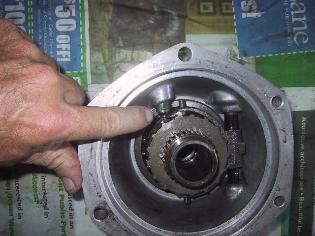
 My middle finger is disengaging the 2wd lever. This forces the shifting gear outward on the splined hub to prevent it from engaging the driven gear hub. Note the fork and shaft on the right side. |
 Moving the 2wd lever forward (lever obscured by cover) with my finger pushes the shifting gear forward along the splined hub....
|
 ...which would then allow it to mesh with center teeth of the driven gear hub above, providing power to the sidecar axle/wheel via the splined hub. |
 To remove the 2wd shifting gear, pull the gear up while rotating it towards the fork shaft... |
 ...in this view you can see the to guide pins on each tip of the fork that ride in the groove of the gear... |
 ...now roll the shifting gear CCW to free it from the guide pins. |
 Mark each guide pin...
|
 ...top... |
 ...and bottom so you get them back in there original position, then remove them. |
 With the shifting gear removed you can see the yoke, lever shaft and #7000111 (55X90X11) bearing. This is not a common bearing and will be easier and cheaper to get through your URAL dealer. |
 To remove the yoke, you will need to remove this cotter pin. |
 Use a pair of needle nose pliers...
|
 ...then slide the 2wd engagement lever shaft free. |
 Place the pieces in your parts box. |
 Next, use a long thin flat blade screwdriver to pry up/off the C-clip holding the splined hub in the outer cover. |
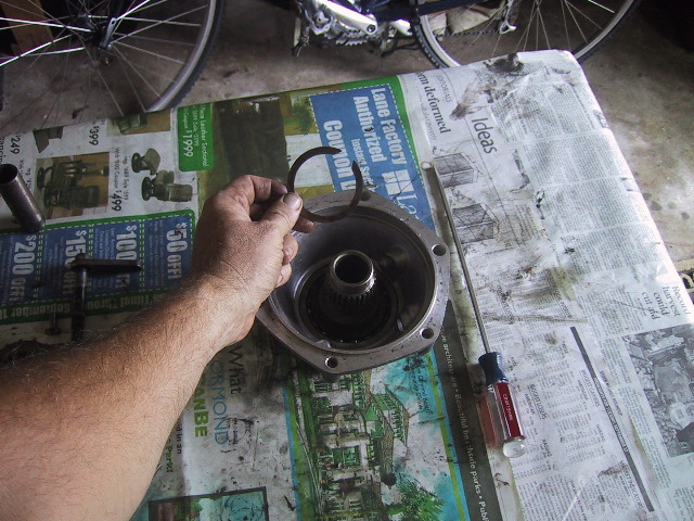 Clip is removed! |
 The splined hub can now fall free so use caution.
|
 Set the splined drive aside. |
 The #7000111 bearing is now ready for removal. |
 Place the housing down and use a tommy bar and hammer ... |
 ...to tap around... |
 ...the outer face of the bearing race...
|
 ...in a 12, 6, 3 and 9 o'clock pattern...
|
 ...until the bearing falls free. |
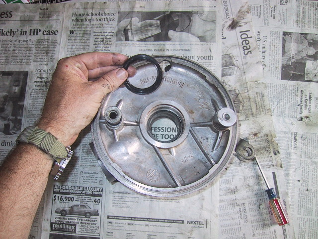
 Turning the housing over you will now have access to the 55X80X10 seal (same as used for rear main bearing on engine). |
 Use a pair of pliers... |
 ...to pull it free.
|
 Bearing and seal removed. |
 Now you can remove the 2wd lever shaft seal. This seal is 11.5X12.1X7 and only available through your URAL dealer. |
 Just pop it out with a screwdriver. |
 The outer cover is now completely stripped. Place the parts in your parts box. |
7.6(d): Splined Hub Disassembly
 Retrieve the splined hub and remove the #204 bearing. |
 If you don't have a pilot bearing puller, use a 19mm socket and long extension... |
 ...open the jaws of a vise... |
 ...so you can set the splined hub atop it with enough spread to allow the bearing to clear... |
 ...and then tap it through with the socket and a hammer. |
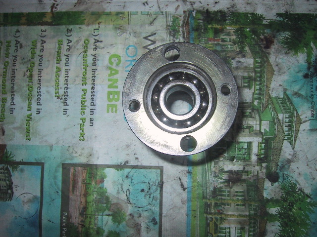
 Front face of bearing. |
 Inside face of bearing. Note the cut out in the bearing race at 6 o'clock. This type of bearing is a high capacity bearing, the notch is where extra balls are inserted. Do not confuse this bearing with a standard #6204. Ask for a #204 high capacity. |
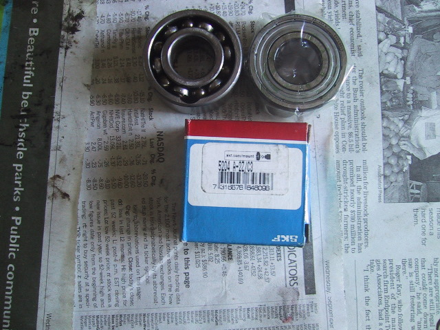 Here is the new #204 bearing to the right of the old Russian bearing. Always order you bearings "sealed" if available. In some applications, one or both seals may be left in place as an additional oil seal. The seals are easily removed with a screwdriver or pick. |
Toss the disassembled splined hub back in the parts box. |
7.6(e): Driven Gear Disassembly
 Retrieve the driven gear hub for disassembly.
|
 Another view of the worn teeth on the hub. This causes a bit of slop with the rear wheel hub.
|
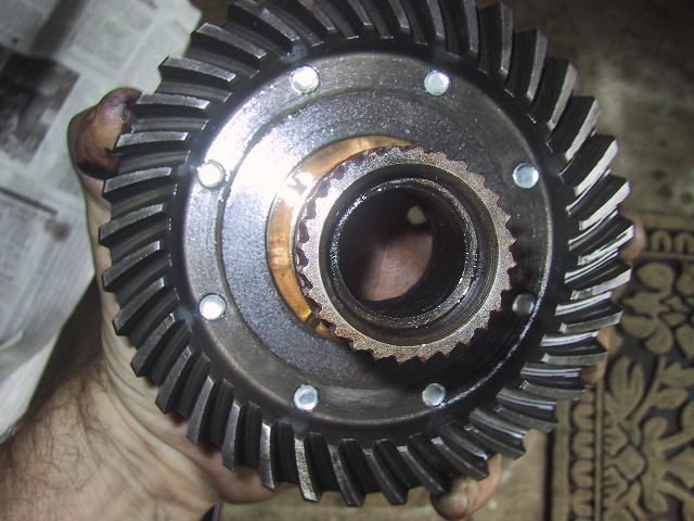
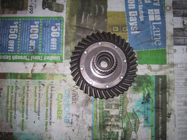 Front view of the hub showing the ring gear on the outside edge.
|
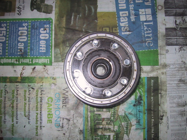
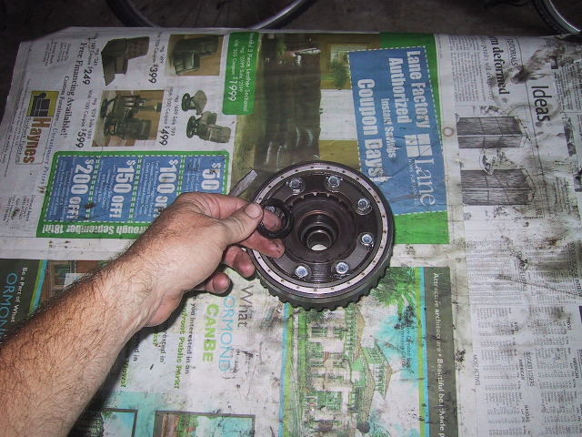
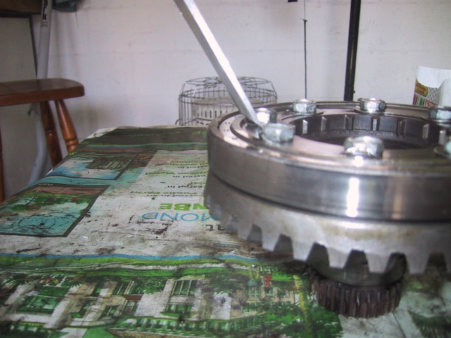
To start disassembly, turn the hub over. You can see the eight 12mm bolts and 4 half moon lock washers with hold the ring gear to the hub. |
 Use a screwdriver to pull the 25X36.4X7 (fractional and only available through your URAL dealer) free.
|
 Under this seal you will find...
|
 ...a...
|
 ...spacer.
|
 Seal and spacer removed.
|
 Spacer and seal line up like so inside hub. |
 Next, use a wood chisel...
|
 ...to bend down...
|
 ...the half moon lock washer tabs.
|
 Use a tommy bar to set them flat.
|
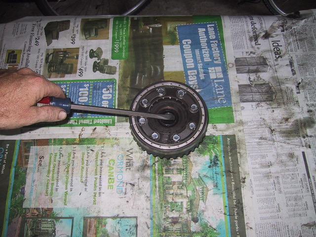
 Use a 12mm socket and ratchet wrench... |
 ...to remove the 8 bolts.
|
 Rap the hub on the floor to release the ring gear.
|
 Can't get enough of these shots showing the worn teeth...
|
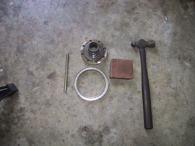
 All that is left is to remove the #1000822 (110X140X16)bearing from the hub. This bearing cost $360 dollars aftermarket so I suggest you buy the $80 Russian if you need to replace it. |
 Use a block of wood that is smaller than the inside diameter of the #1000822 bearing (110mm)...
|
 ...place the hub on top of the block of wood...
|
 ...use a tommy bar and hammer to tap around the inner bearing race in a 9 o'clock... |
 ...3 o'clock...
|
 ...12...
|
 ...and 6 o'clock pattern until the bearing...
|
 ...is free. Hint: It is sometimes easier to lay the palm of your punch hand on top the splines and rotate the driven hub 90 degrees after each strike with the hammer. |
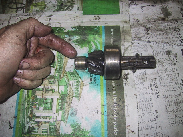
Place the disassembled driven hub in a parts box and get the pinion drive out for disassembly.
|
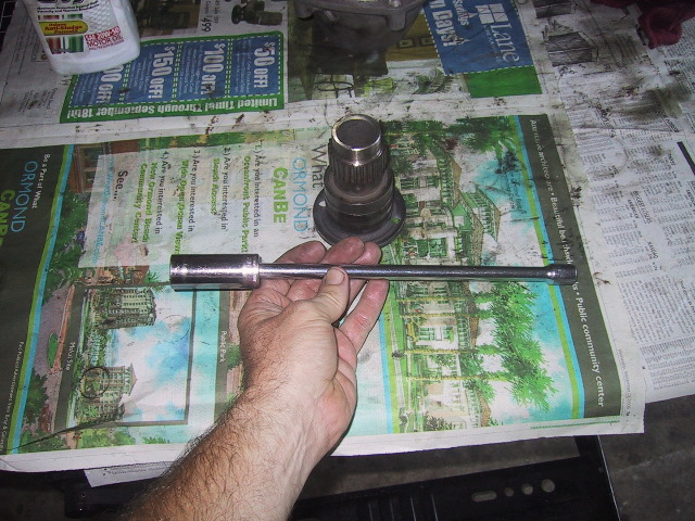
7.6(f): Pinion Gear Disassembly
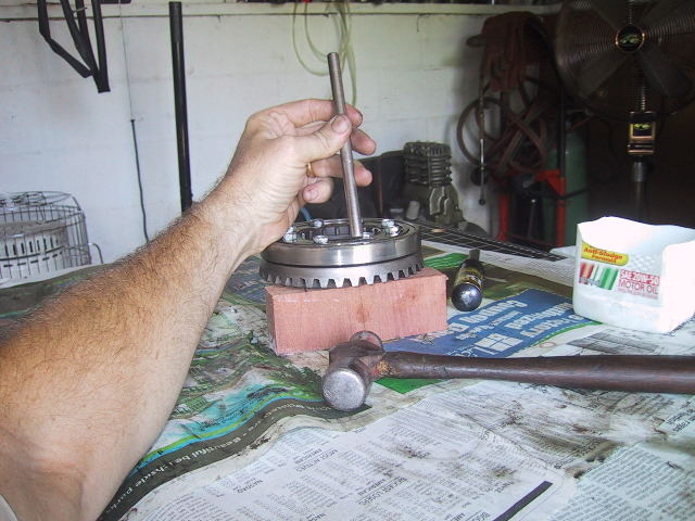
 If you have access to a floor press or arbor press, removing the #5304 bearing and inner needle bearing race is a piece of cake. If you don't have either of the above, this method will work just as well. |
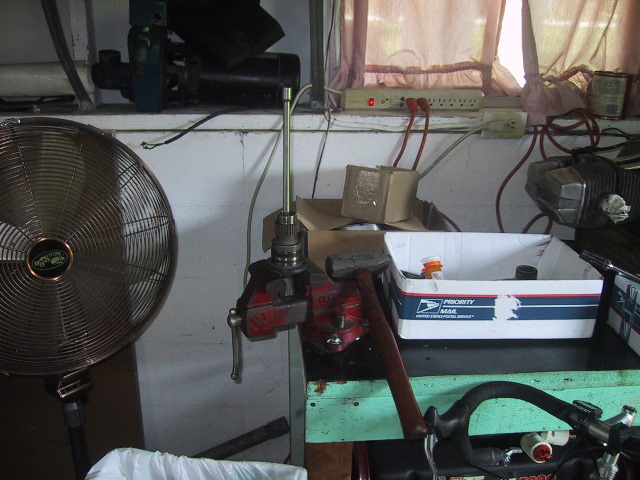
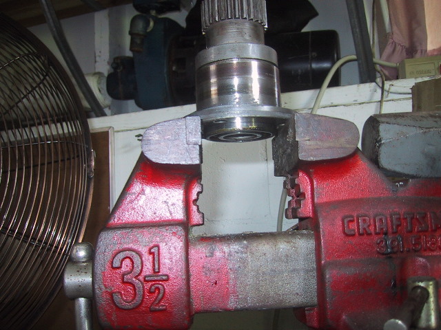
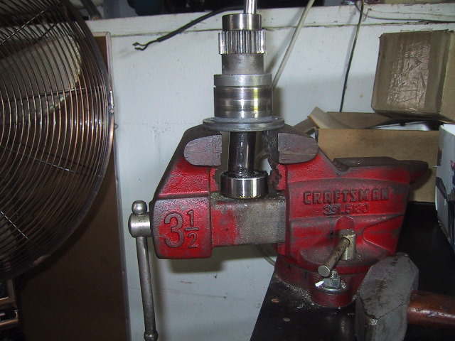
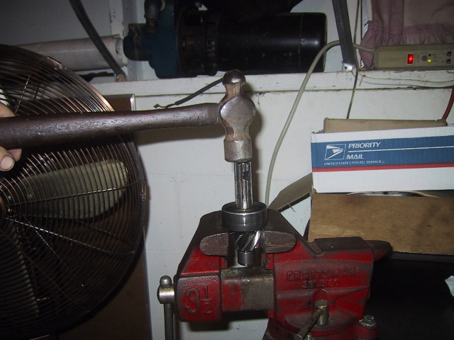 Spread the jaws of a vise so the bearings inner race is resting on the jaws...use a hammer to tap the pinion gear shaft through the bearing. |
 If you plan on reusing the gear...make sure you put something under the vise to catch it so it does not hit the floor and get buggered up. |
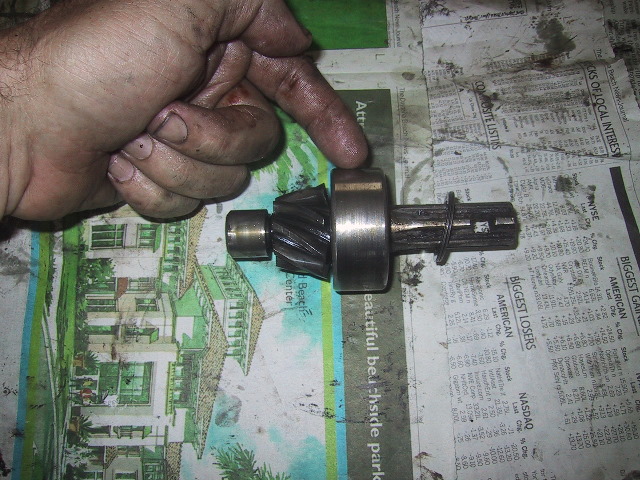
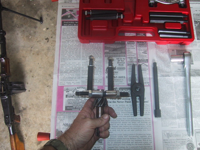
 There is not enough room to use a standard "jaw" type puller, so to remove the inner race of the needle bearing... |
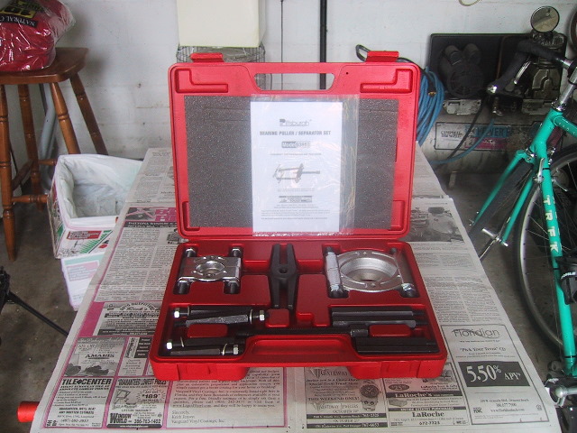 ...I bought a cheapo bearing separator kit from Harbor Freight for $30. Pittsburgh brand #93980. The kit has a 2" and 3" separator and accessories. "Lifetime" guarantee.
|
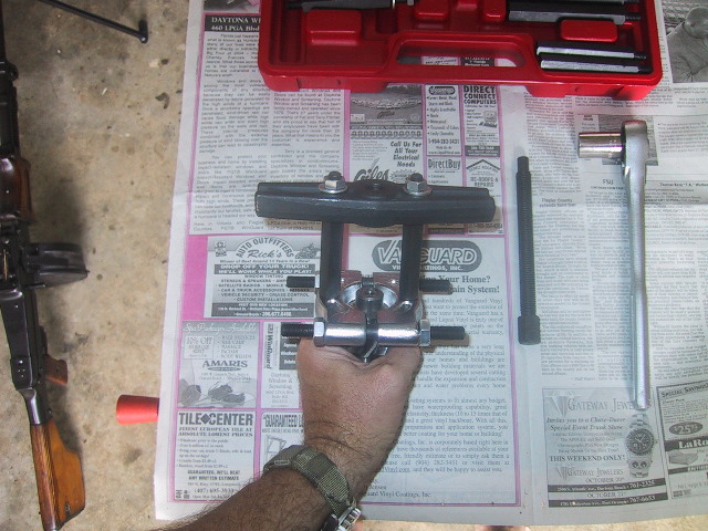
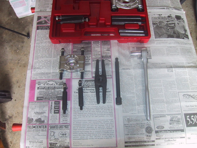 I used the 2" separator, 4" extensions, 6" yoke adapter and the lead screw provided in the kit. I used a 1/2" ratchet with an 11/16th's socket to turn the lead screw. |
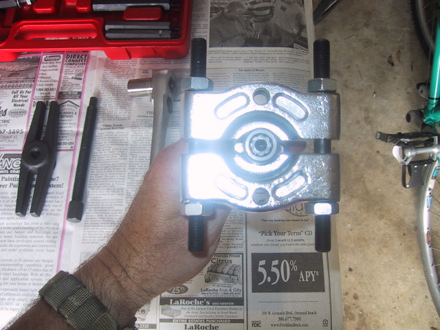 Attach the separator so the blades are under the inner race and in the small gap between the pinion gear and bearing race... |
 ...side view of placement...snug up the nuts so the separator is tight with no play. |
 Next, screw the extension bars onto the separator body... |
 ...then attach and secure the yoke to the extension bars.
|
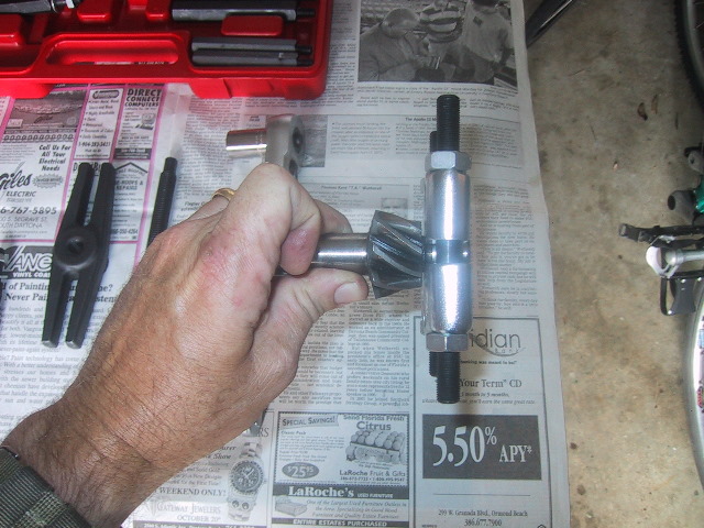
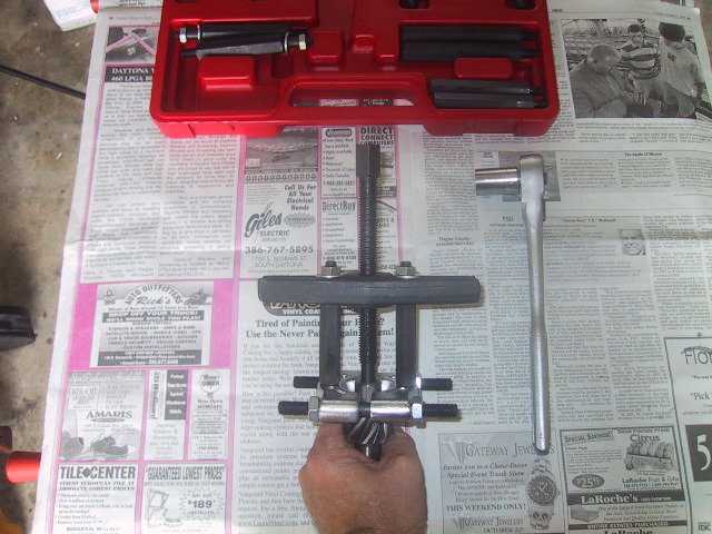 Put a few drops of oil on the lead screw and thread it down until it contacts the face of the pinion shaft. |
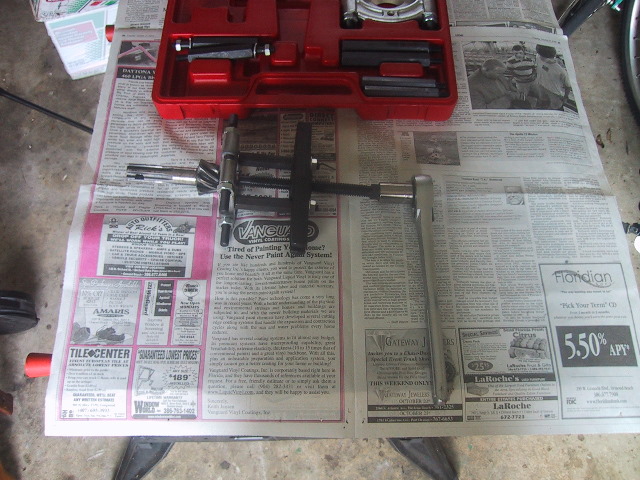 Set the assembly down, hold the separator with one hand while using the ratchet to slowly tighten/press the lead screw in. |
 With no effort at all the pinion is pushed free of the assembly. Be sure not to let the pinion gear fall. |
 Disassembly of the final drive is now complete. |
|
|