|
|
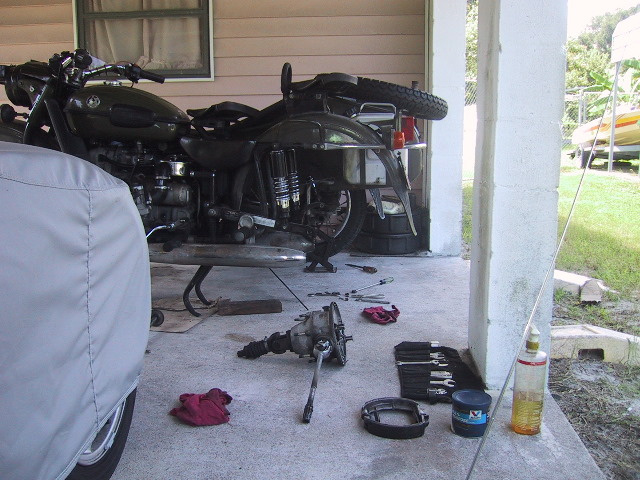
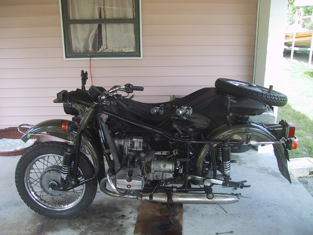
Engine Removal
Tools Needed: Oil and gas catches/basins, 19, 17, 13, 12, 10 mm wrenches, Pliers, large flat blade screw driver, 8 & 3mm Allen wrench, 19 mm socket & long extension, Ural pin spanner, hammer, tommy bar, floor jack and misc. pieces of wood.
Time Required: 3 hours
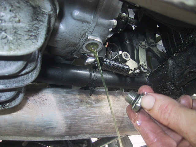
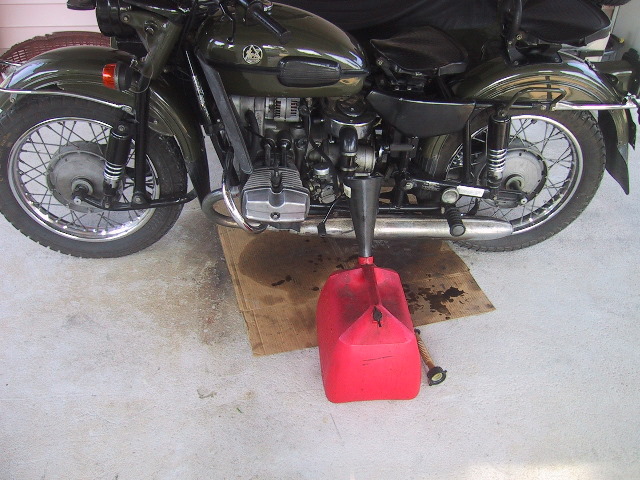
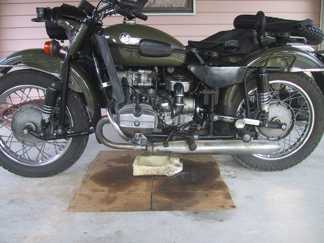 Place an oil catch under the engine sump and... |
 ...drain the oil. Replace drain plug. If you have a deep sump installed you must remove it in order to clear the frame. It would be wise to install the standard sump to protect the oil pump during engine removal or installation. |
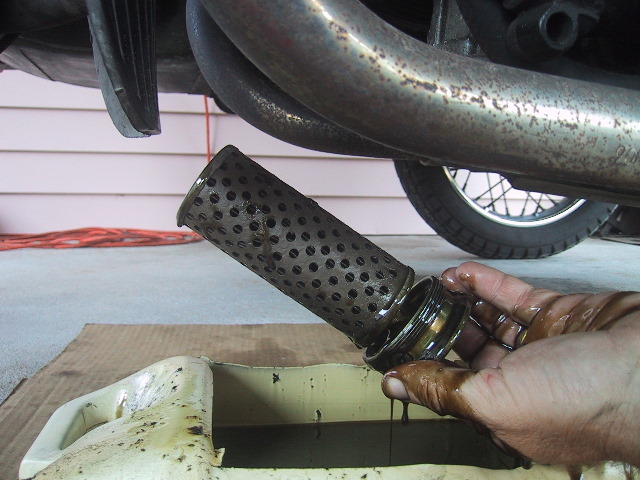 Remove filter and drain oil from filter sump. Replace filter and re-install. |
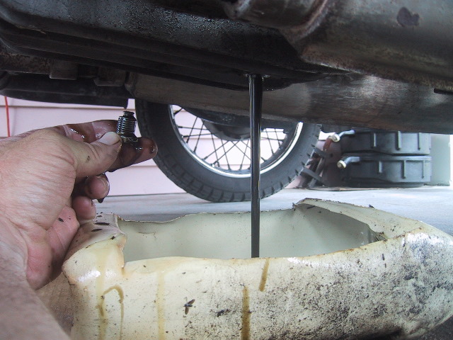
 Place oil catch under gear box sump and drain oil. Replace oil drain plug. |
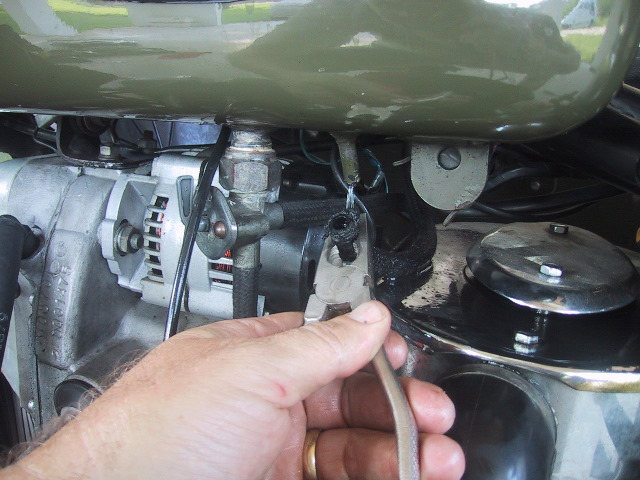
 With petcock in "Off" position, pull fuel line from left carburetor and place line in drainage container. Turn petcock on and drain fuel from tank. |
 When fuel tank has drained, remove right carburetor fuel line at carb. |
 Use pliers or large screwdriver blade to work one end of the fuel cross-over tube free. Use caution as residual fuel will spill out. |
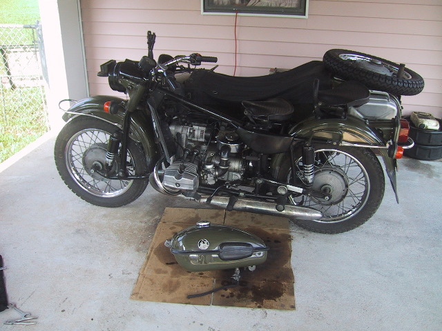 Remove fuel tank. Refer to Chapter 9.2 |
 Remove rear wheel (Chapter 2.6) and remove final drive as shown in Chapter 7.2. |
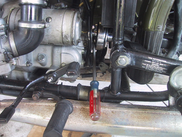 Use a large flat blade screw driver or pry bar to... |
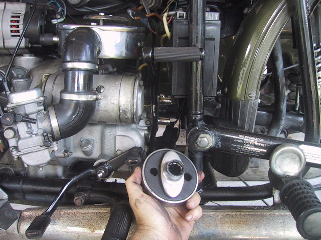 ...remove the rubber flex coupler. |
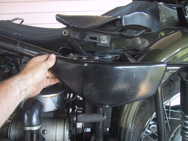 If installed, remove the decorative side cover. |
 Turn the master battery switch to the "Off" position or disconnect the battery as applicable. |
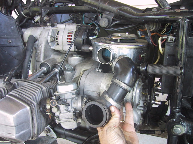 Use a screw driver to loosen and remove the left and right branch tubes. |
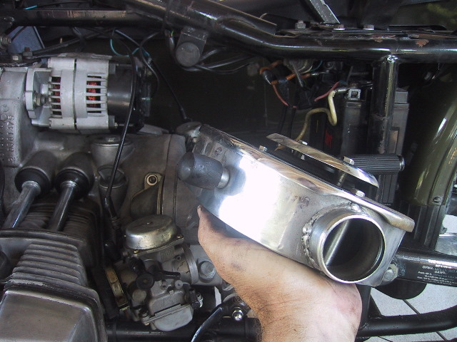 Use a 13 mm wrench and 8 mm Allen wrench to remove the air filter housing. Refer to Chapter 9.4. |
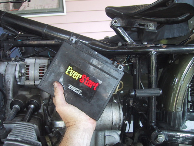 Remove battery. Refer to Chapter 8.3. |
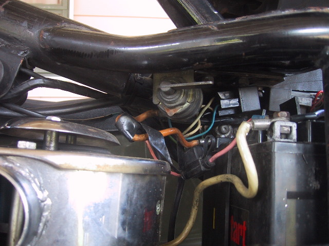
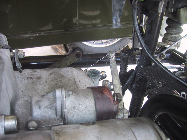
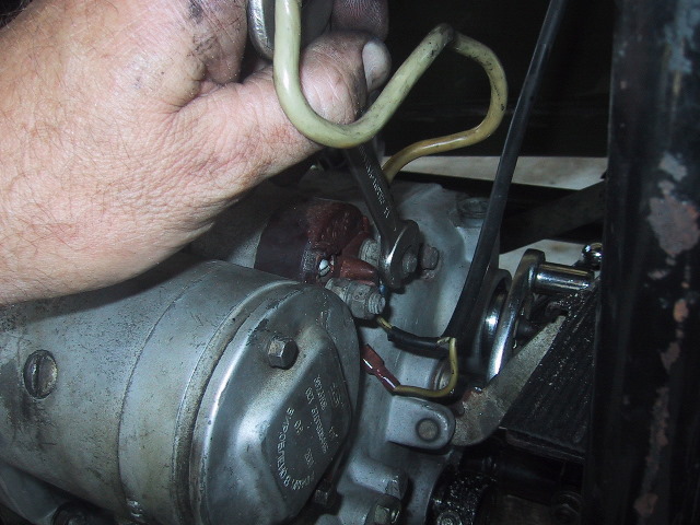 Use a 13 mm wrench to remove all wires from the starter solenoid. Do not forget the small spade push-on wire on the back of the solenoid (just visible below nut & stud). |
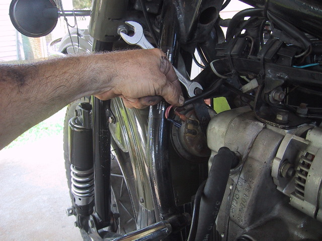
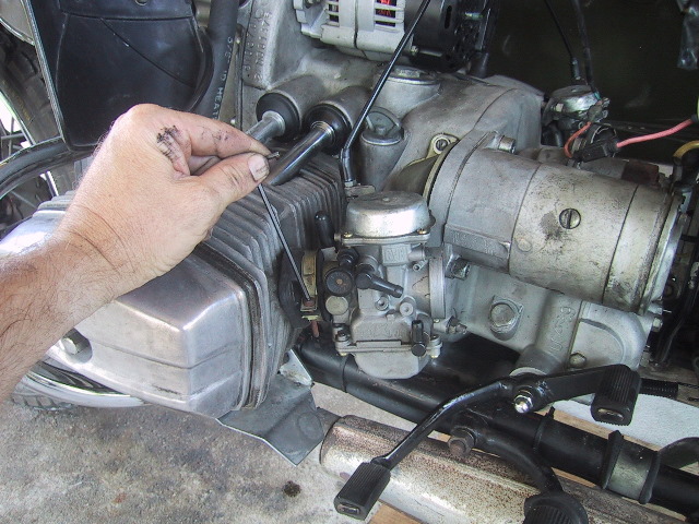 Remove left & right carburetors at the compliance fittings, in this example, a 3 mm Allen wrench is needed. |
 Place both carburetors up out of the way. Draped over the handle bars or resting over the hack are safe places for the carbs. |
 Use a 13 mm wrench to remove the neutral switch indicator wire. Place or tie it off so it will not get damaged during engine removal and replacement. |
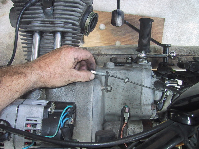 Use a 13 mm wrench to loosen the lock nut on the forward clutch adjustment bolt and remove it from the bracket. The bracket will be needed if you are installing a new factory engine. |
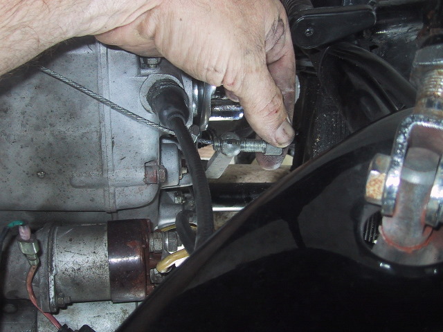 Use the 13 mm wrench to loosen the lock nut on the aft clutch cable adjustment screw and remove it from the clutch release arm. Place or tie off the clutch cable so it will not get damaged during engine removal and replacement. |
 Use a 10 mm wrench to loosen the speedometer cable lock screw if applicable... |
 ...remove speedometer cable by pulling straight up. Tuck the speedometer cable up into the frame where it will not get damaged during engine removal and replacement. |
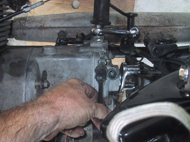
 Tie the clutch release arm forward so it is not free to move during engine removal and replacement. It can easily be bent or broken if allowed to flop around. The clutch arm will be needed if installing a new factory engine. |
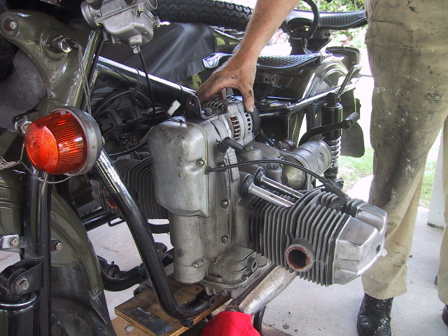
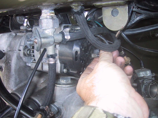 Remove the spade connector on the back of the 35A alternator. The Denso alternator will have two spades. |
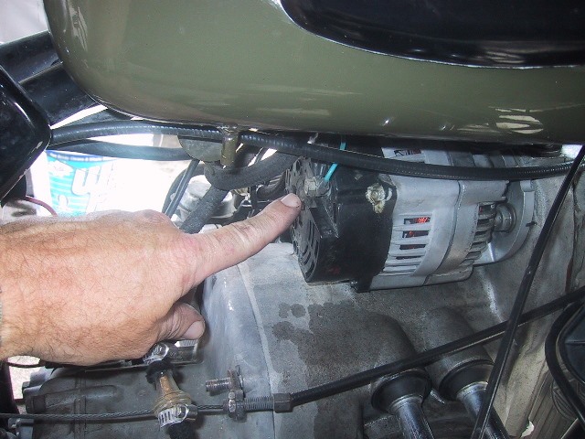 Use a 10 mm wrench to remove the nut holding the wires to the back of the 35A alternator. The Denso's wiring stud in located on top of the alternator on the right side, sometimes under a rubber cover. Place or tie off these wires to the frame to prevent damage during engine removal and installation. |
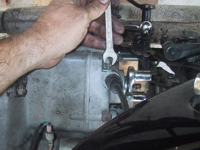
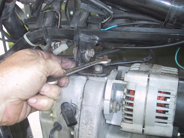 Use a 13 mm wrench to loosen the top engine mount base nut and remove any wires attached. Place or tie off these wires to the frame to prevent damage during engine removal and installation.
|
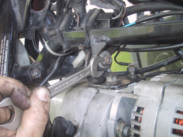 Use a 12 and 13 mm wrench to remove...
|
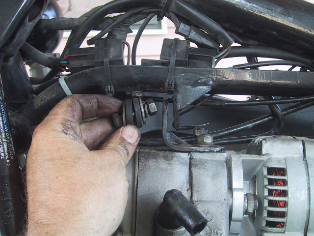 ...the top engine mount bolt, washers and rubber grommets.
|
 Pull the connect apart for the 12v coil hot wire going into the front cover.
|
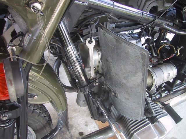 If installed...
|
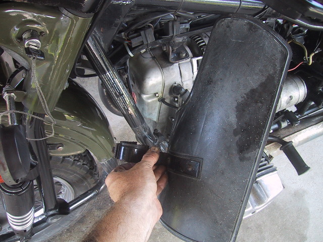 ...use a 12 and 13 mm wrench to remove left and right leg guards.
|
Pull the wires to the horn and use a 12 and 13 mm wrench to remove the nut holding the horn to frame. Replace nut and washer on bolt. When remounting horn, it does not matter which wire goes in which position. |
 Use a 17 mm wrench to remove the top nut to the cylinder guard.
|
 Use a 19 mm socket and long extension to remove the front left engine mounting bolt nut. This nut secures the bottom of the cylinder guard also.
|
 Remove the cylinder guard and put the 17 mm nut back on the top mount of the guard.
|
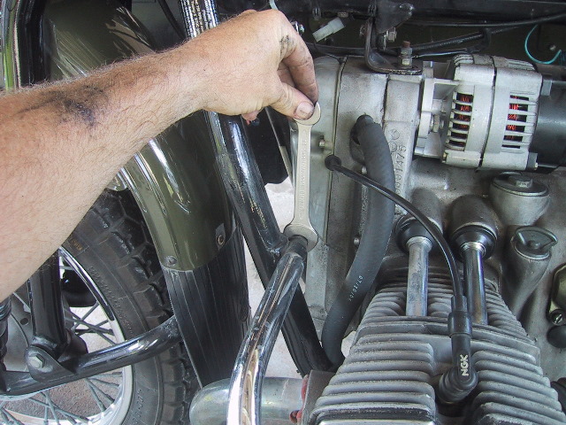
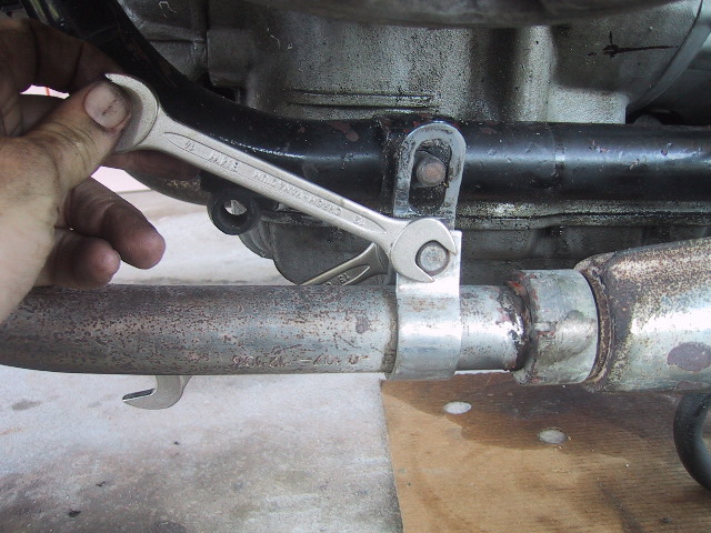
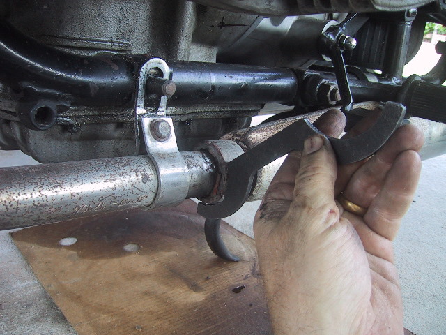 Use the Ural tool kit pin spanner to loosen the exhaust collar nut on each exhaust.
|
 Using a 12 and 13 mm wrench, loosen both the left & right exhaust header clamps.
|
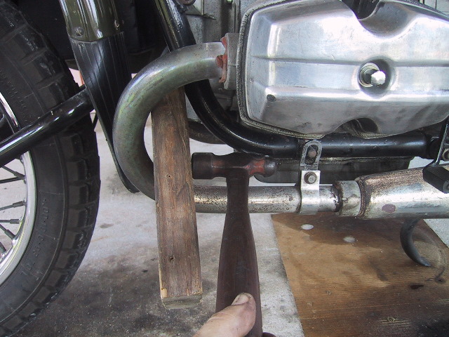 Use a dead blow hammer or block of wood and hammer to tap the exhaust out of the cylinder head. 2006 year model and newer heads have bolt on header pipes.
|
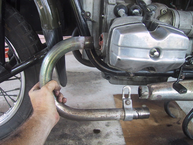 Remove header pipe.
|
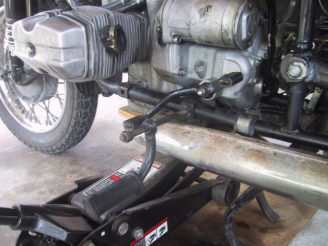
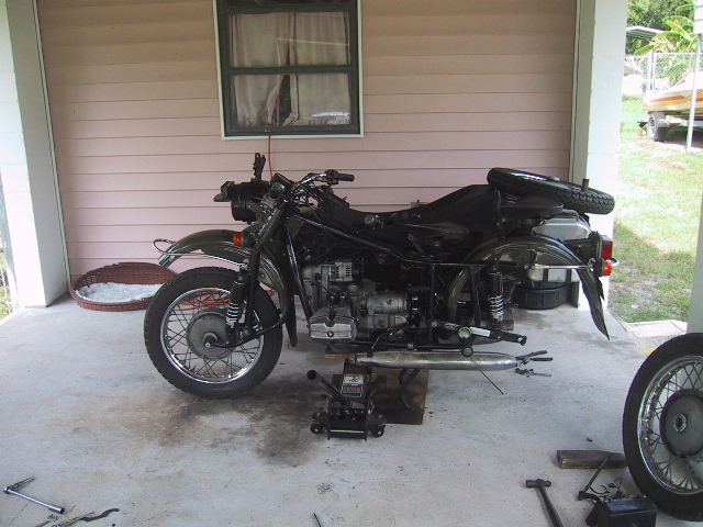
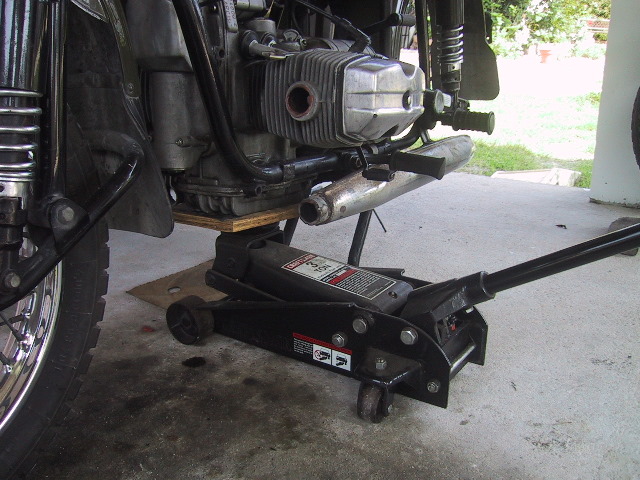 Place a square piece of plywood on a floor jack and adjust the jack so it just supports the engine.
|
 Use a 19 mm wrench to remove the right rear engine mounting bolt nut and foot peg.
|
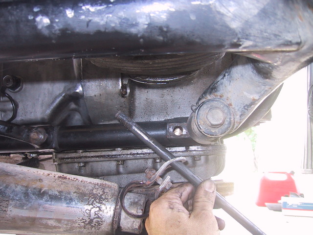
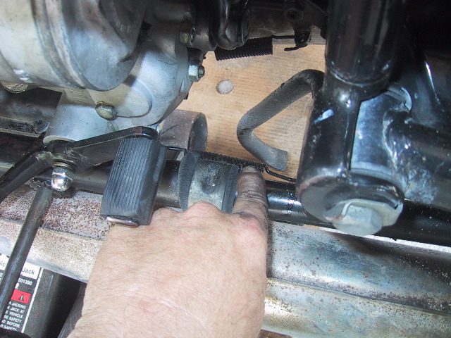
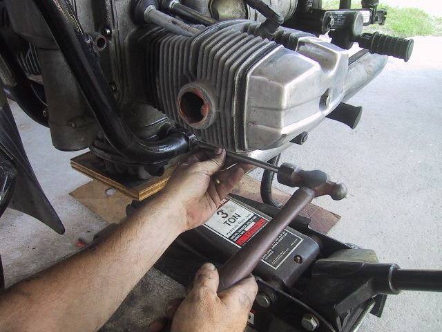 Use a tommy bar and hammer to drive the forward engine mounting bolt from left to right through the frame.
|
 Do not drive the tommy bar all the way in. When you withdraw the tommy bar, catch the forward engine spacer so you do not lose it. Be sure to slip the spacer back in before re-inserting the engine mounting bolt back through on reassembly. |
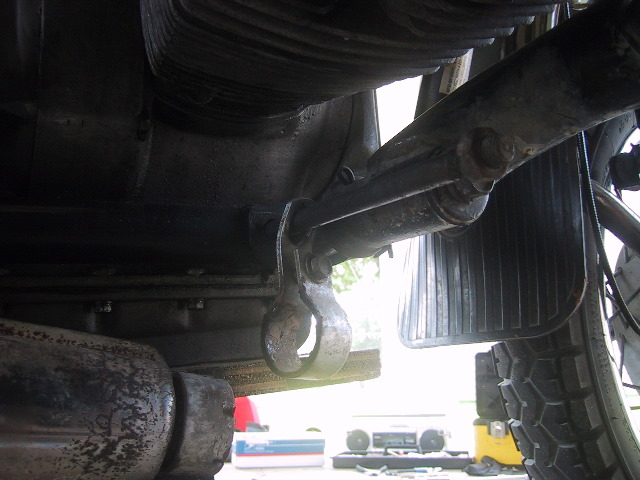 Crawl under the forward end of the sidecar... Take the hammer and tommy bar with you.
|
 ...and withdraw the forward engine mounting bolt and exhaust header clamp from the frame. You may need a helper to jiggle the engine to get the bolt to slide free. Remember to slip the exhaust clamp on before reinserting the engine mounting bolt on reassembly.
|
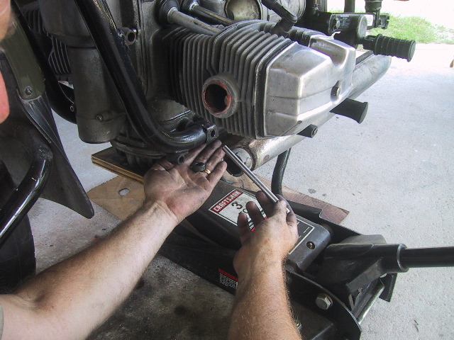
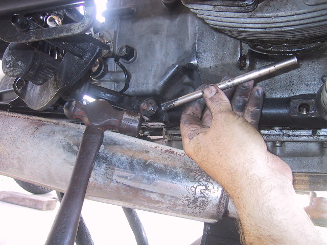 While still under the sidecar, use the tommy bar & hammer to drive the rear engine mounting bolt from the right to left. You again may need to adjust the engine with the jack or have a helper jiggle the engine to get the bolt to move easily.
|
 Remove the right foot peg.
|
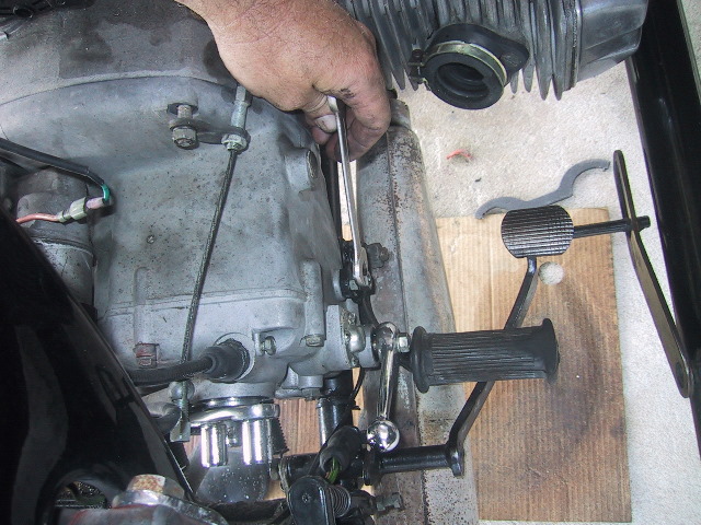
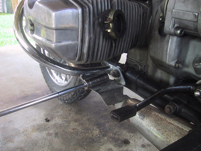
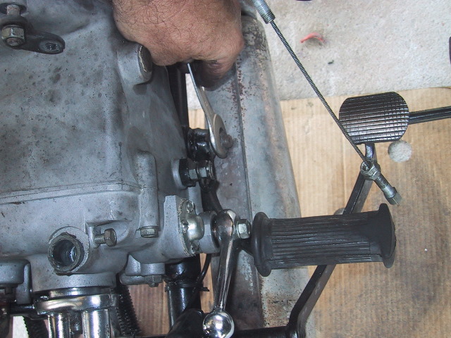
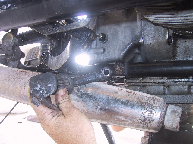
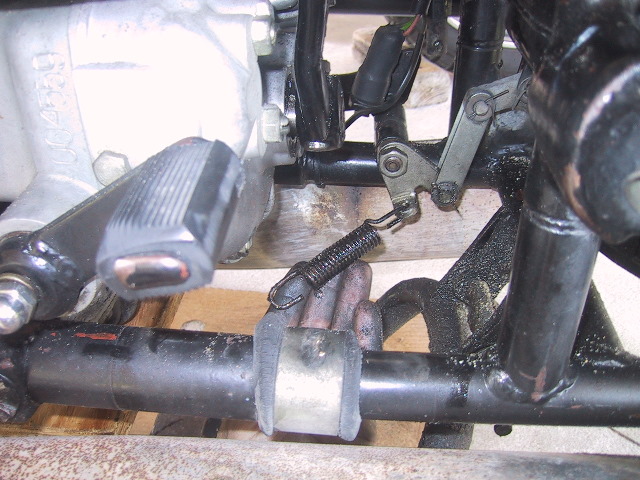
 The rear engine mounting bolt can be seen under the foot shift lever. Note the rear engine spacer and end of the...
|
 ...return spring for the center stand.
|
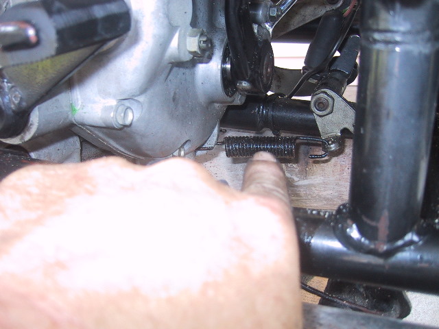 To the right of the center stand spring is the return spring for the foot brake. All three of these items will fall free when the rear engine mounting bolt is remove and/or the engine is moved.
|
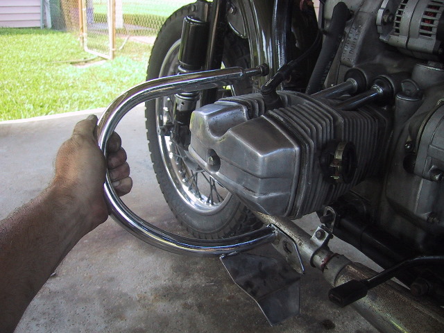
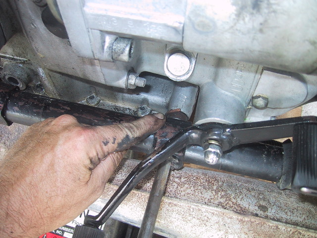
 Grasp the left foot peg and twist the rear engine mounting bolt free of the frame.
|
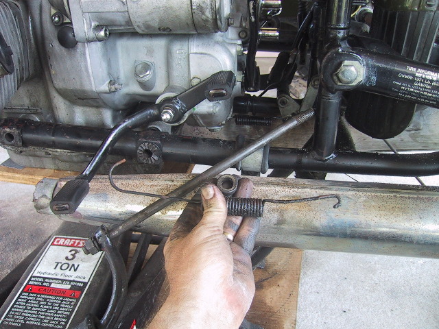 Spacer and center stand spring after falling free. Do not forget to put the spacer back in before reinserting the rear engine mounting bolt. Both spacers go on the left side of the frame.
|
 Foot brake return spring has already slipped off its boss. On reassembly, use a long pair of curved needle nose pliers or brake spring pliers to hook the two springs to their respective bosses.
|
 Engine is now supported only by the jack and plywood.
|
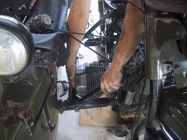 Unless you are built like Boris, you will need two people to remove the engine from the frame. One person must lean over the seat and grasp the right cylinder... Be careful to not pinch your fingers between the cylinder and sidecar frame!!!!
|
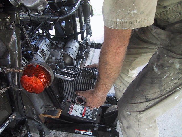 ...the other person grabs the left cylinder. Tilt the left cylinder down enough to clear the top of the engine from under the top of the frame. Lift the engine out at a 30 to 45 degree angle until the engine oil sump is clear of the frame...
|
 ...then rest the sump on the left side of the frame. The person holding the right cylinder can now reach through the left side of the frame and grasp the cylinder/gear box or kick start lever while the other person continues with the left cylinder... |
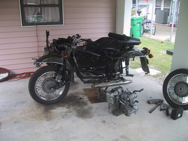 ...and finish moving the engine out of the frame. You should set the engine down on some wood so as to not damage the sump cooling fins. Installation is the reverse steps. |
|
|