|
|
|
|
Gearbox Disassembly & Reassembly
Note: Clutch release mechanism already removed. See Chapter 6, section 3.
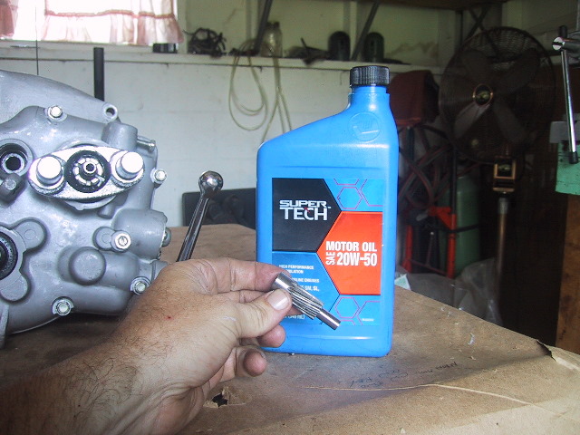
Tools Needed: Long needle nose pliers, 12mm, 10mm socket & ratchet, 13mm wrench, hammer, tommy bar, wood chisel, wire cutter, bearing separator, adjustable wrench and wood blocks.
5.5(a) Disassembly of Gearbox
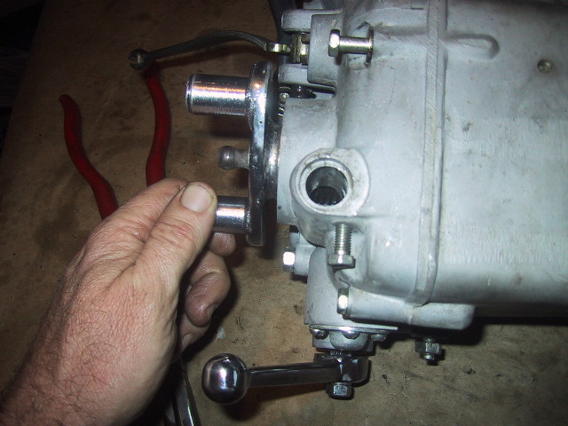
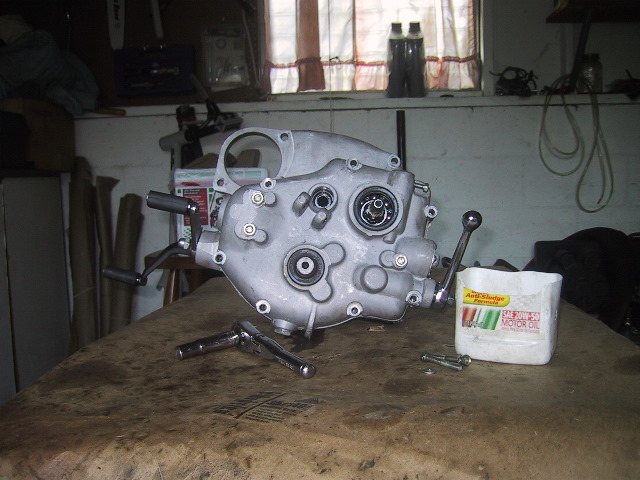
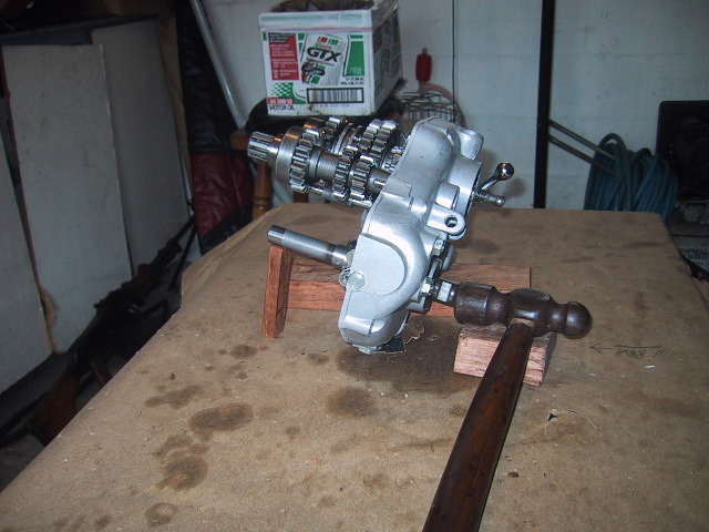
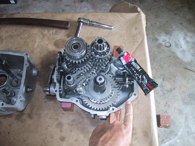
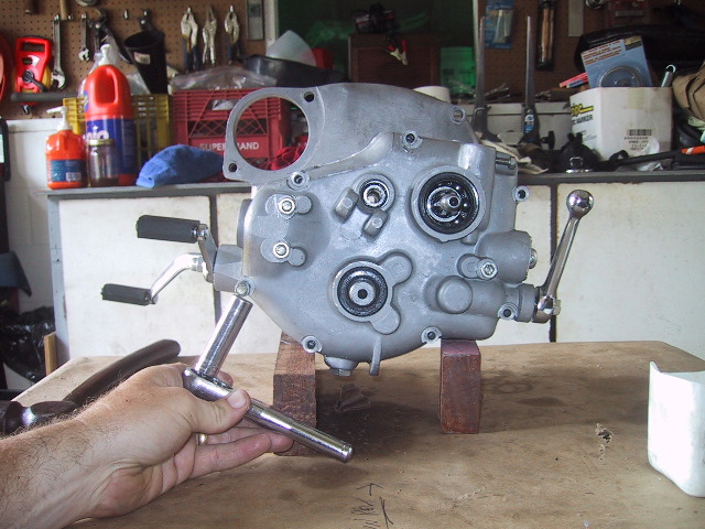
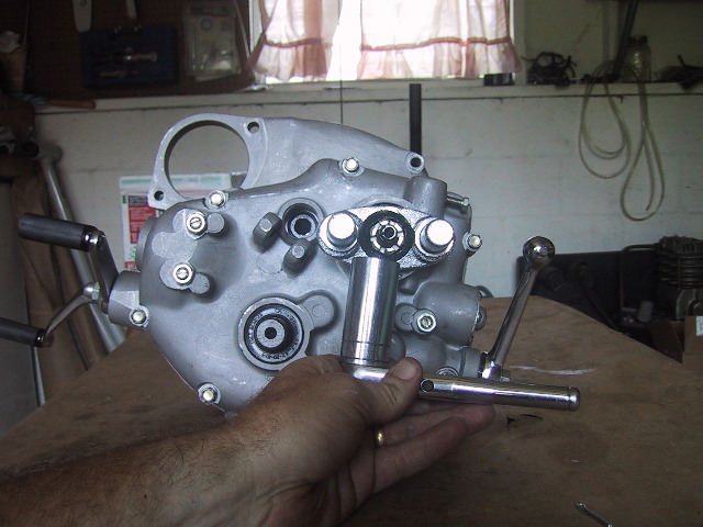
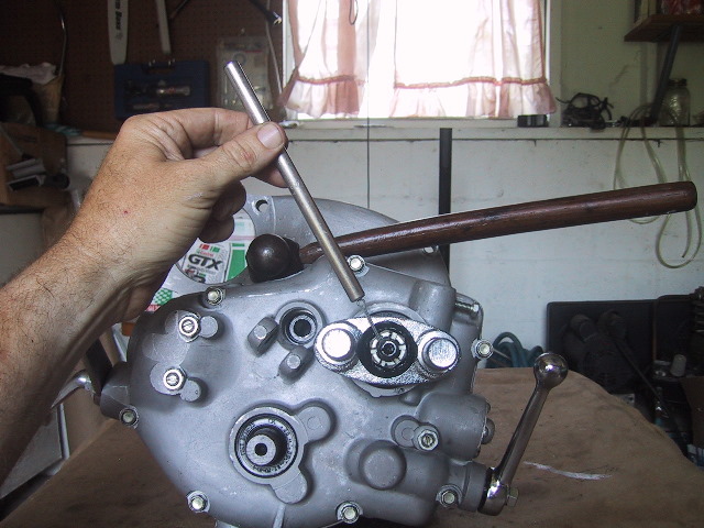
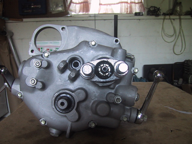
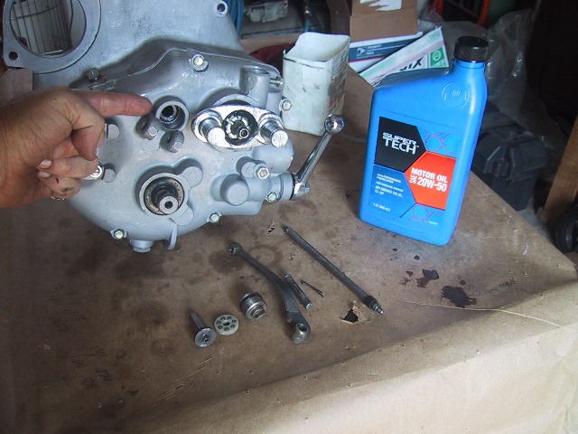
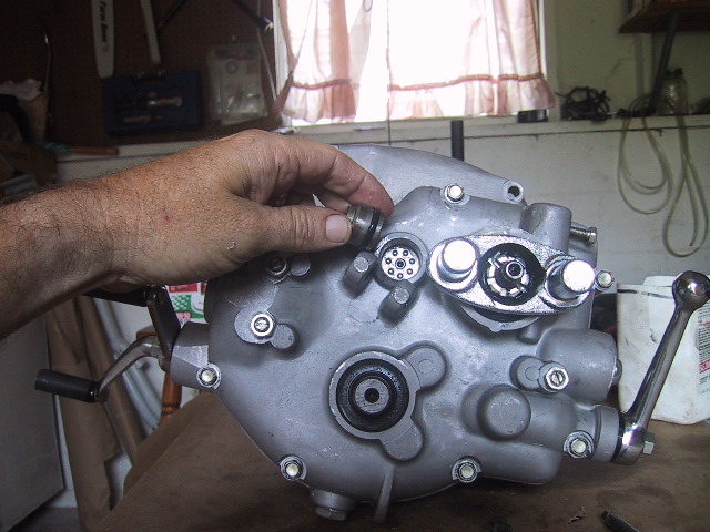
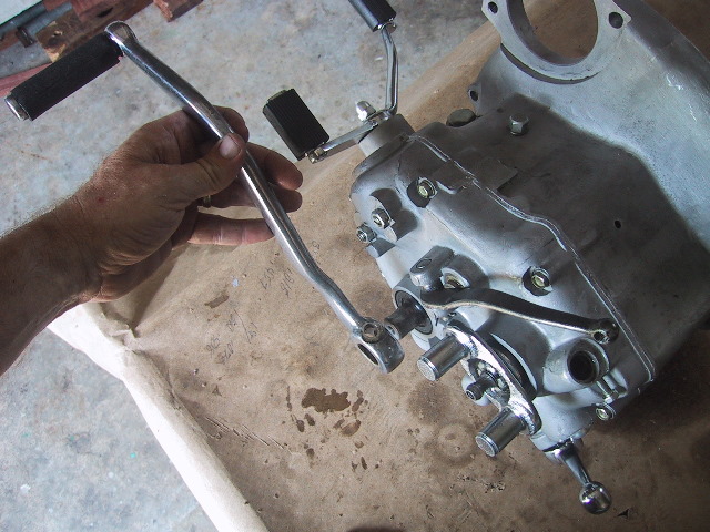
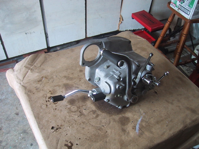
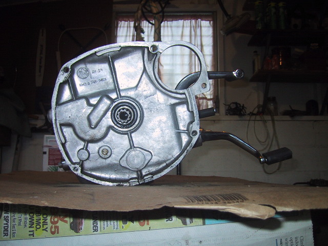 Four view of the gear box. Front showing the splined clutch shaft in the middle... |
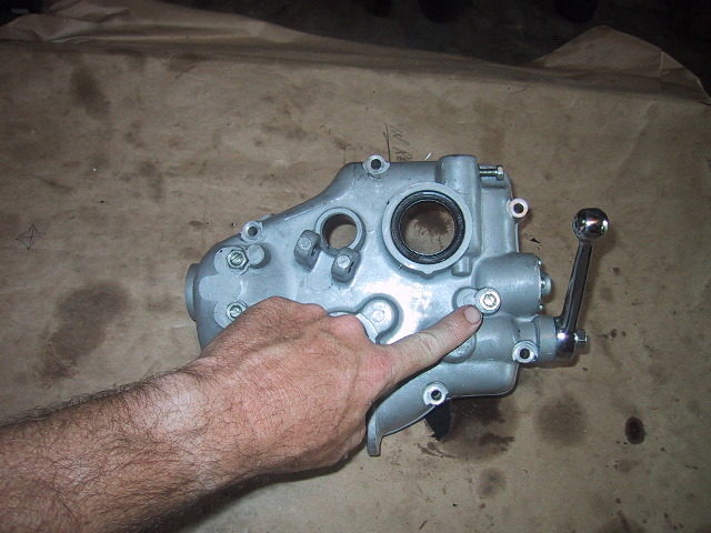
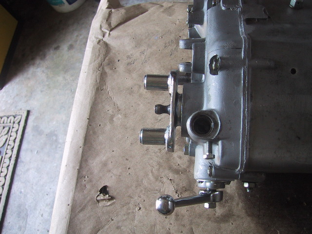
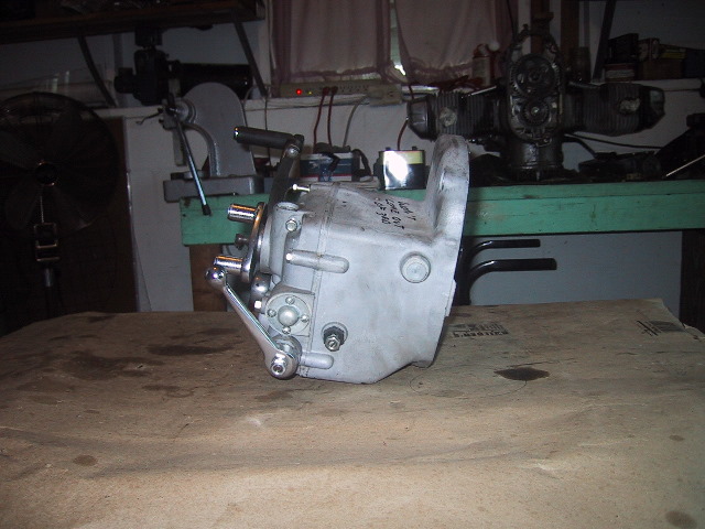 ...right side showing reverse/neutral shift lever and neutral switch. |
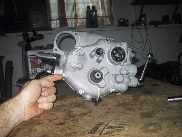
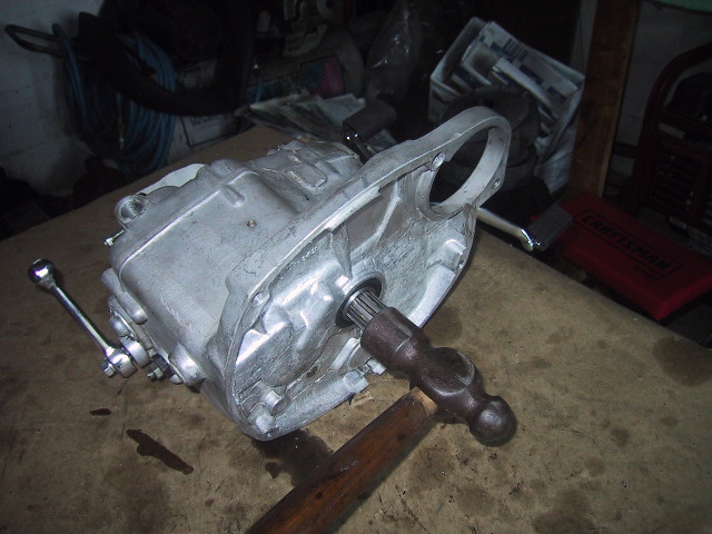
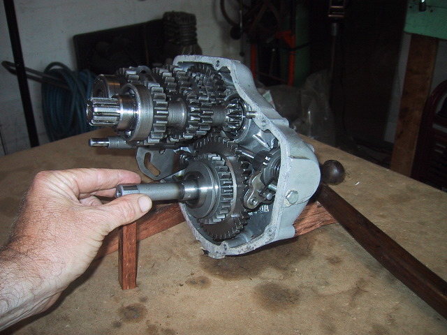
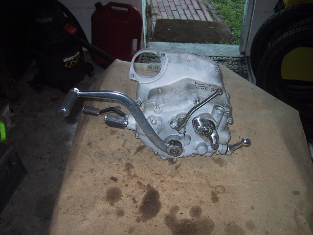 The rear of the box showing the kick start lever, clutch release arm and flexible coupling plate (yoke) on the main shaft... |
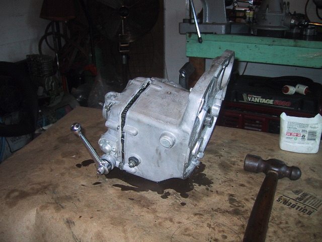
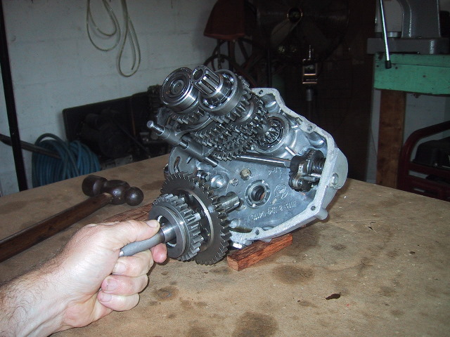
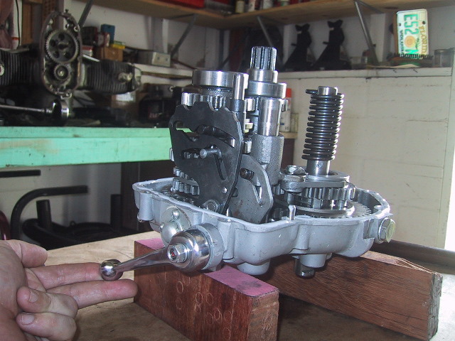
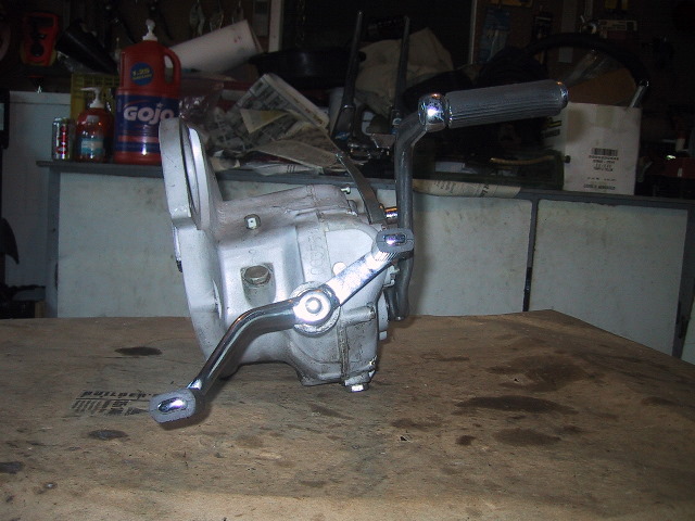 ...and finally the left side of the box with the foot shift lever. On top is the vent screw, underneath that, the filler cap can be seen for the oil and below the drain plug. |
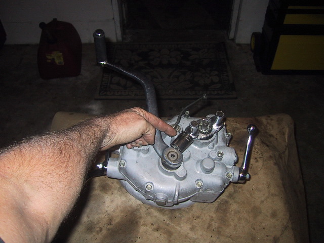
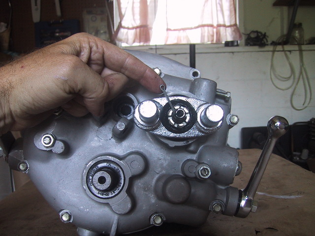
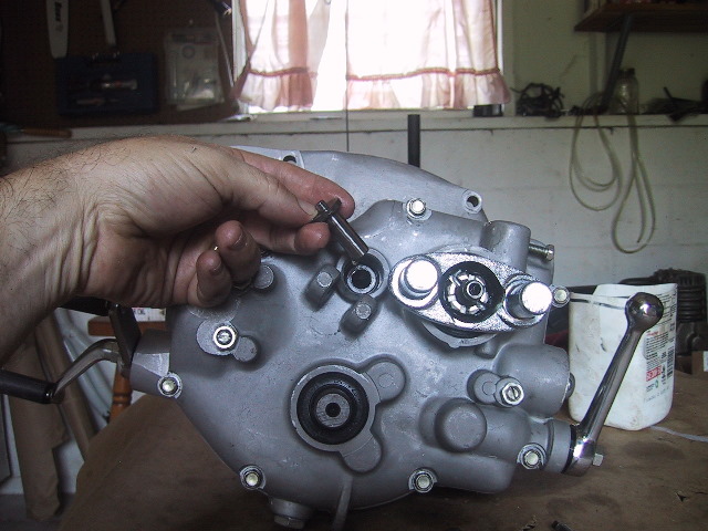
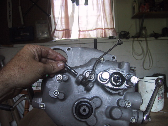
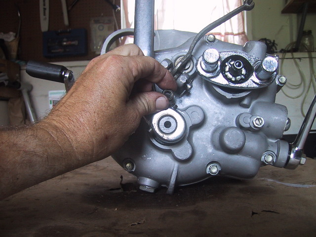
 Start the disassembly by removing the speedometer gear. Back out the speedo cable retaining screw by hand or use a 10mm wrench. |
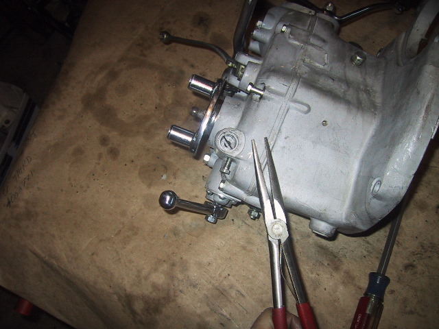 Use a long pair of needle nose pliers to... |
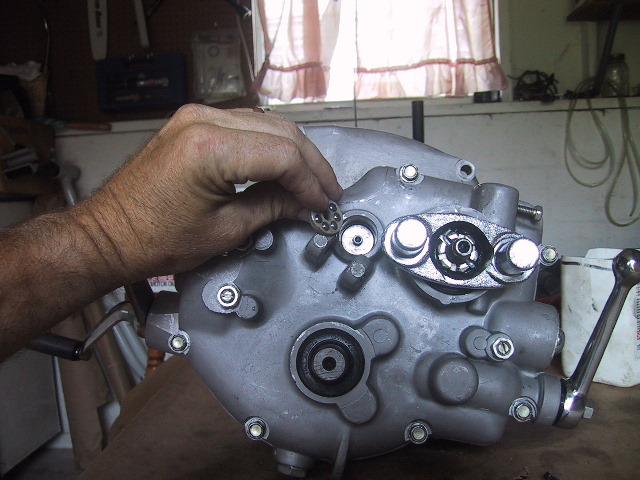
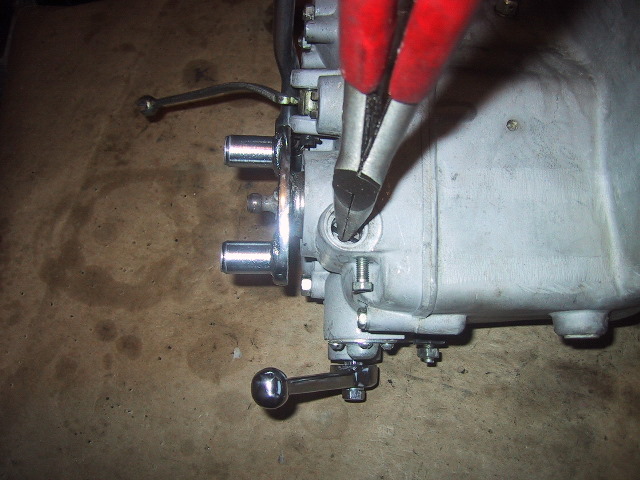 ...reach down in and spread the pliers apart... |
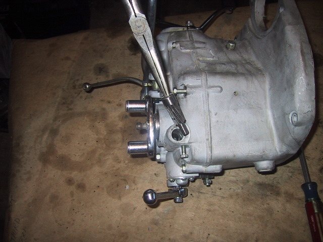 ...and carefully lift out the speedo drive gear. You may need to turn the flexible coupling plate slightly to disengage the gears. |
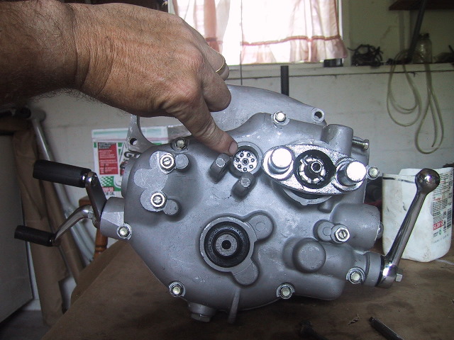
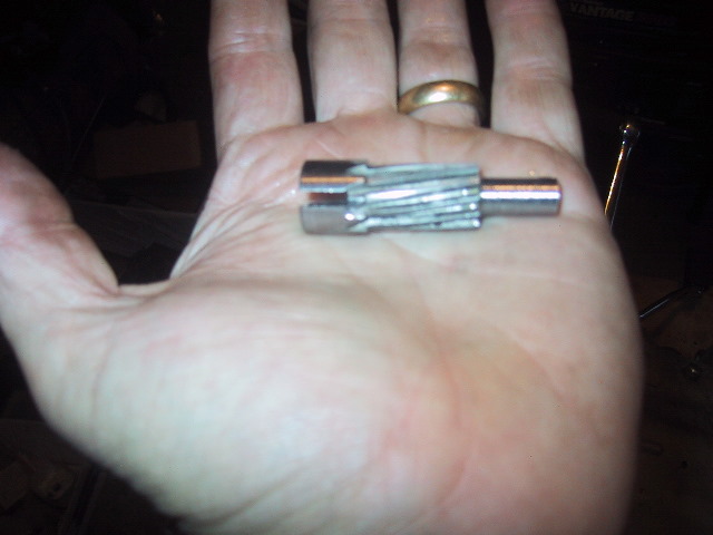 Speedo drive gear removed. Place it in a parts box so it will not get lost of damaged. |
 You can just barely see the drive gears of the flexible coupling plate, these are what engage and turn the speedo drive gear. |
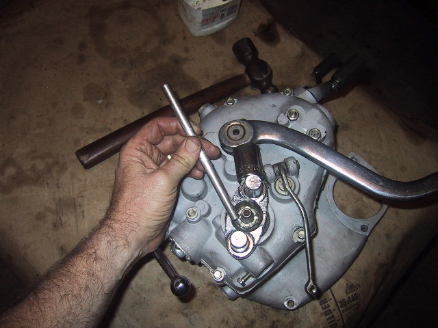
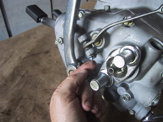
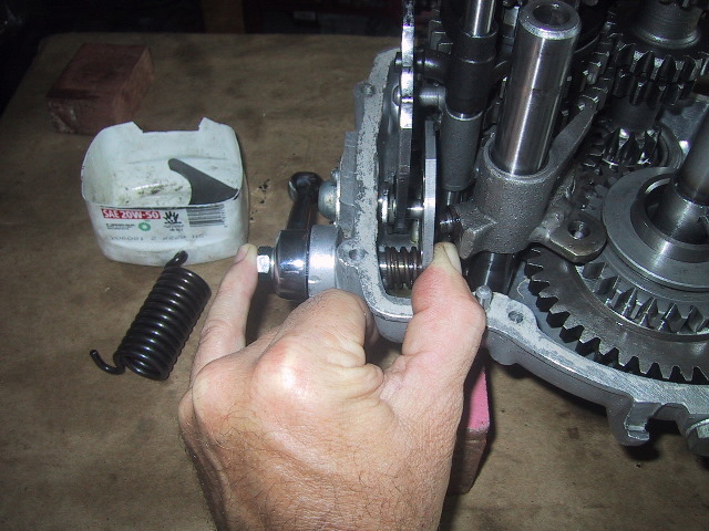
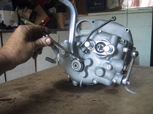
 To remove the flexible coupling plate, this cotter pin must be removed. |
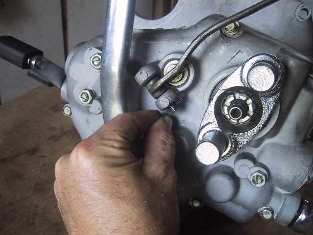
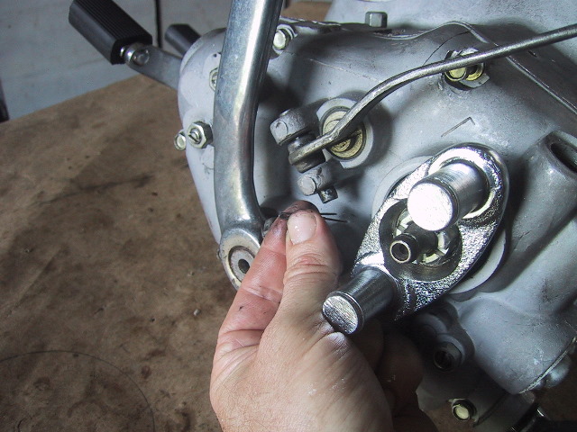
 Use a pair of pliers or cutters to bend the cotter arms straight and then... |
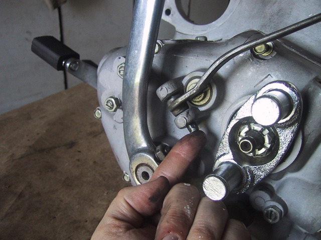
 ...pull the cotter pin out. |
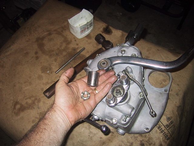
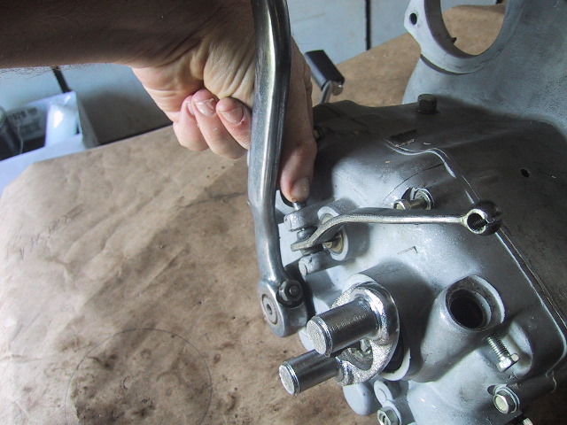
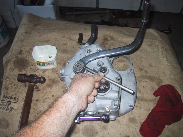
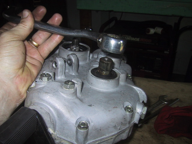
 If the box is in neutral, block the fork with a socket or wood between the kick starter arm to keep the coupling plate and main shaft from turning. |
 Use a 22mm socket to loosen and remove the nut and washer underneath. If a socket will not fit, use a tommy bar and hammer on the flats of the nut. |
 22mm retaining nut removed. |
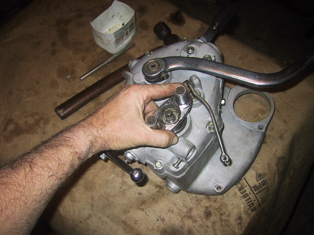 The coupling plate just slips off the splines of the main shaft... |
 ...like so. Careful that the washer under the nut does not fall and get lost. |
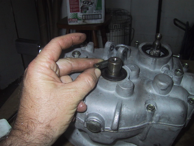
 A closer view showing the gearing on the end of the flexible coupling plate to drive the speedo gear. |
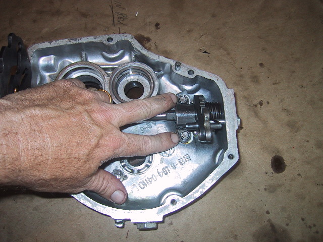
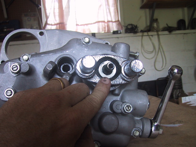
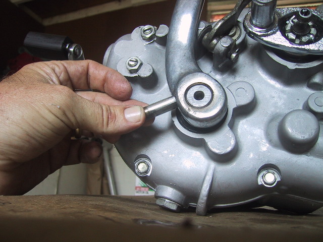
 A view down the main shaft hole showing the #304 ball bearing on the aft end of the main shaft. |
 Remove the clutch release arm next. |
 Use your fingers to squeeze the cotter pin of the clutch lever pin together... |
 ...grasp the head of the cotter pin... |
 ...and pull it free. |
 Use your finger to push the clutch lever pin up... |
 ...and pull it free while holding the clutch lever arm. For further disassembly of the clutch rod assembly refer to Chapter 6.3. |
 To remove the kick start lever start by... |
 ...using a 13mm wrench to remove... |
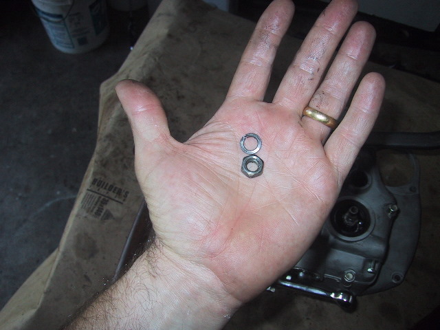 ...the retaining nut and washer. |
 Use a drift or tommy bar and hammer to drive the kick starter lever wedge pin out. |
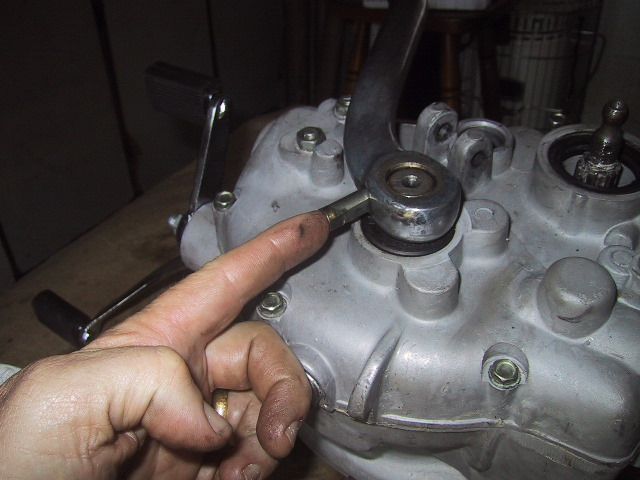 Make a note of the orientation of the "flat" on the wedge pin.
|
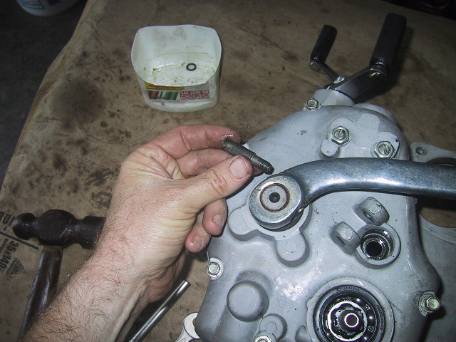 Remove the wedge pin and place it in a parts box. |
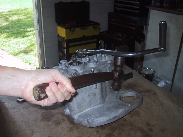 Use a hammer to tap the kick start lever... |
 ...off the kick starter shaft. |
 Note how the flat of the wedge pin seats in the groove of the kick starter shaft. |
 Next remove the 7 10mm bolts that hold the two halves of the gear box case together. |
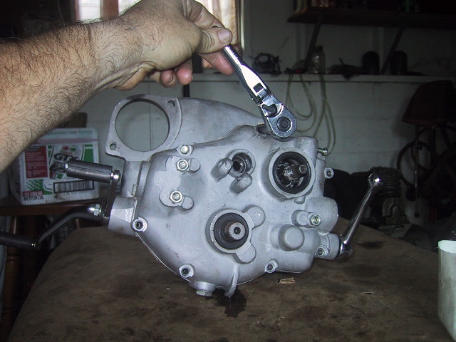 Use a ratchet or wrench whichever is handy. |
 The gear box is now ready to be split. |
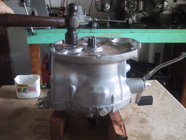
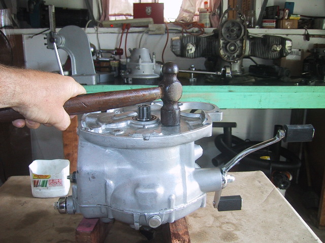
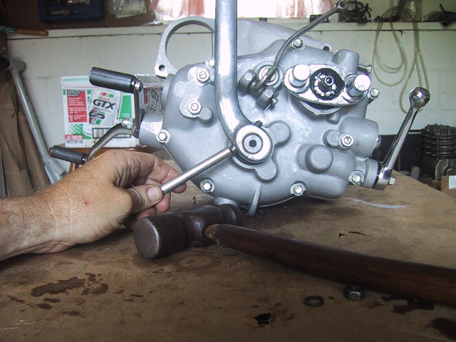
 Use a soft face hammer to smack the end of the clutch shaft repeatedly... |
 ...until the halves separate. |
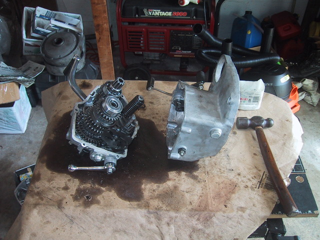 A rap or two more with the hammer and a little jiggling and the halves will separate. |
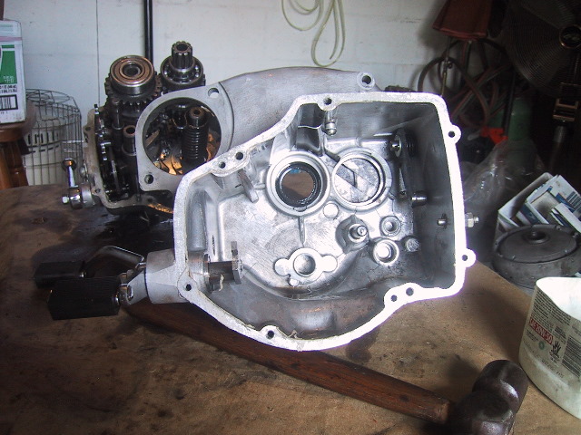 A view of the inside of the front case. Lower left is the foot shift lever. Upper right is the shift quadrant latch assembly. |
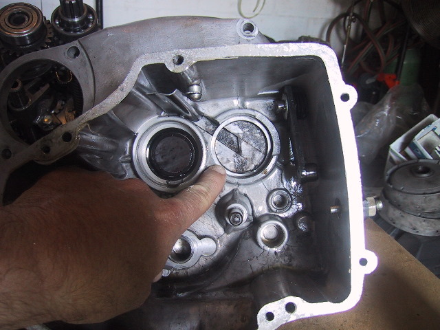 If it/they did not fall out when splitting the case; look here for... |
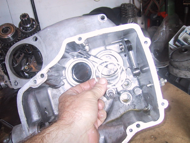 ...the main shaft adjustment shims. They are very thin and easily damaged so be careful and put them somewhere safe. |
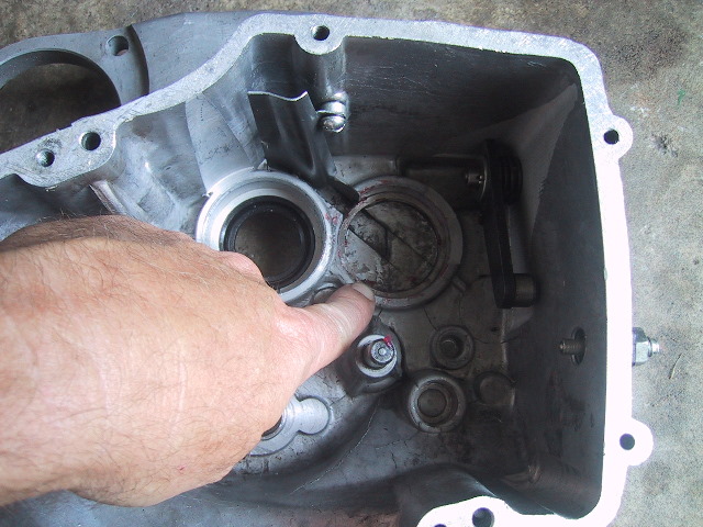
 In the top center of the front cover you will see the oil chute which channels oil to the the front bearing of the main shaft. |
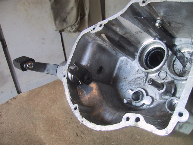 A better view of the gear shift foot pedal shaft. |
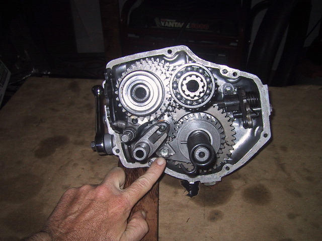
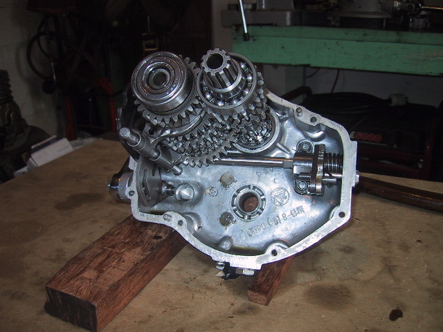
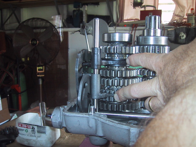
 A right side view of the back half of the case showing the shift quadrants and gear tower. |
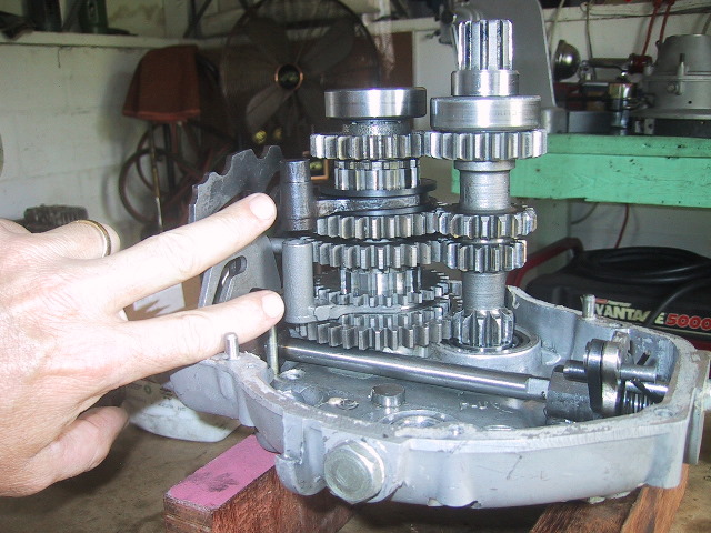
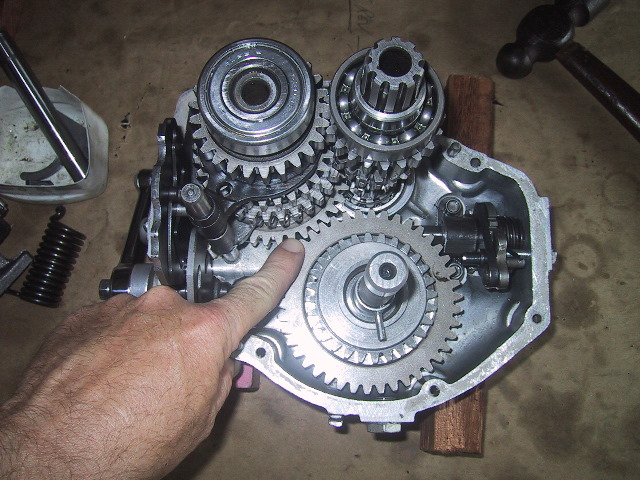
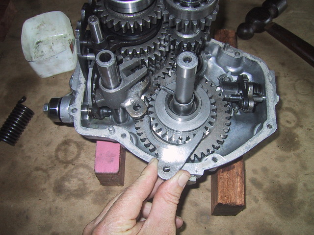
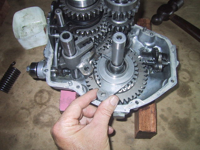
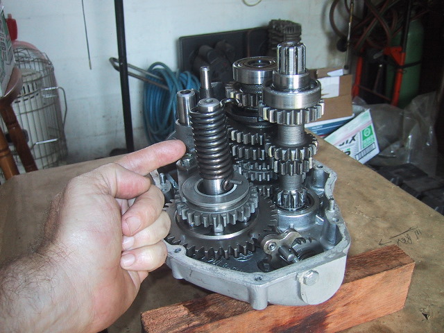
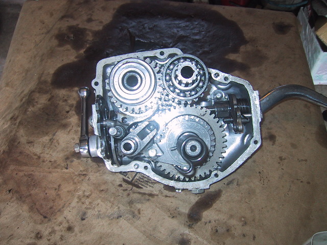 Overhead view of the inside of case. From the upper left clockwise; Main shaft bearing and gears, clutch shaft bearing and gears, gear shift assembly, Kick start shaft and gear, idler bracket and gear and the normal and reverse gear shift quadrants. |
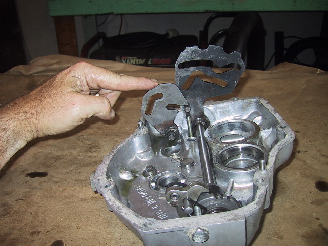
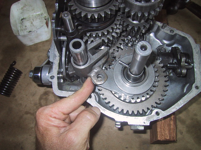
 To begin removing the gear box shafts, start by removing the lock washer and 12mm retaining bolt for the idler gear assembly. |
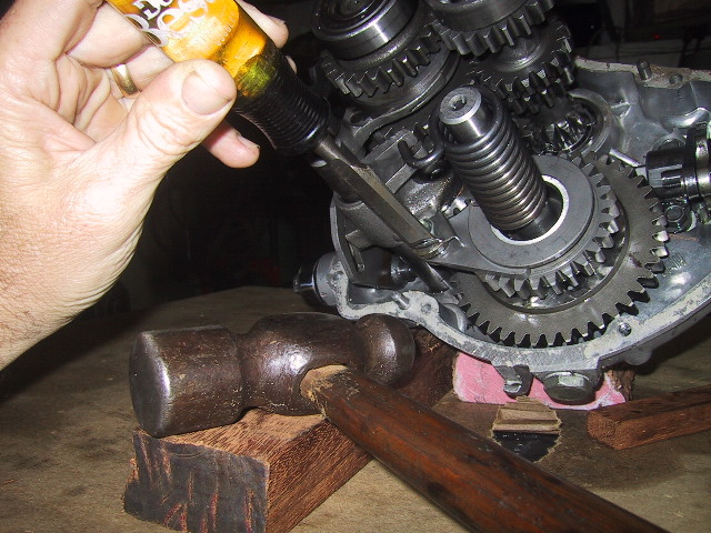 Use a wood chisel or similar tool and hammer to bend the locking tab out... |
 ...and tap it flat with a tommy bar. |
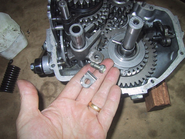
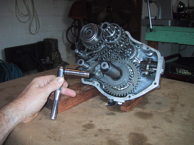 Use a 12mm socket or wrench to loosen and ... |
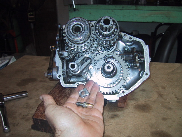 Remove the bolt and lock washer. |
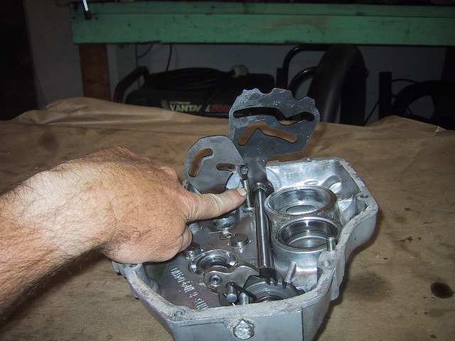
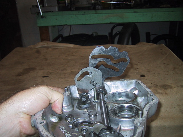
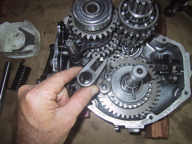
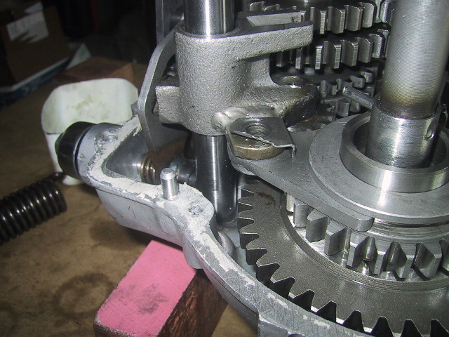
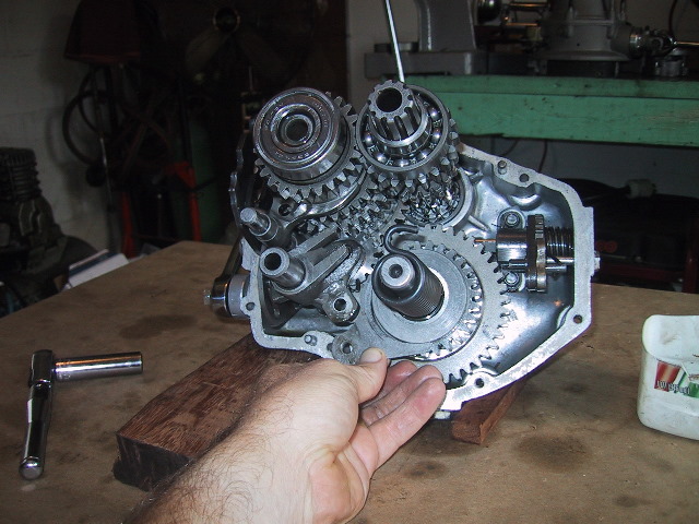 The reverse shift fork will now be free... |
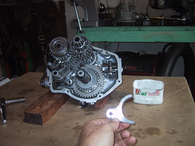 ...and can simply be pulled out. |
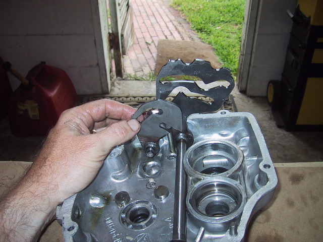
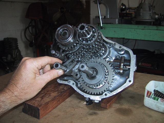 Pull the idle assembly shaft... |
 ...free of the idler bracket. |
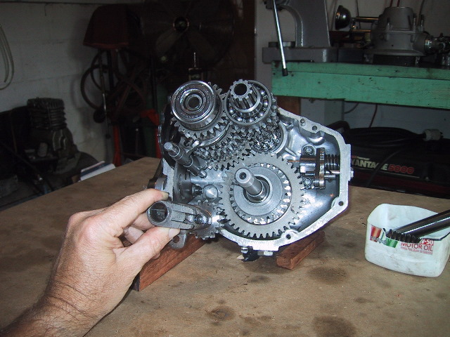 The idler bracket with idler gear can now be removed. |
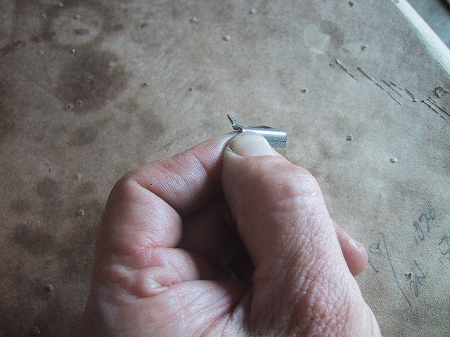
 Be careful to not drop/lose the idler pin from the bracket assembly. |
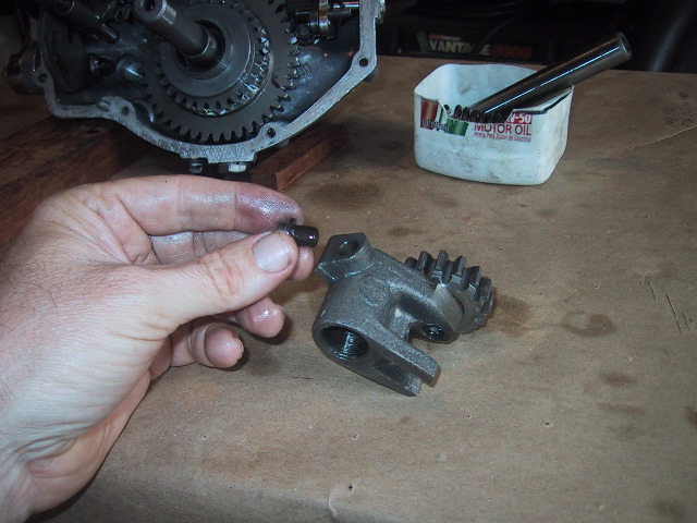
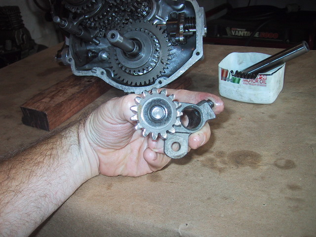 The idler gear is a fixed to the bracket by a large rivet. |
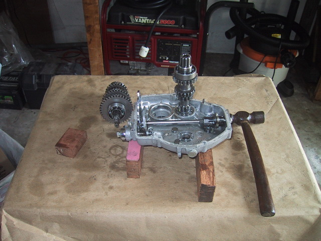
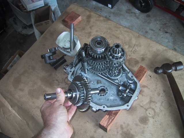
 Use a hammer to tap the kick starter shaft free of the rear housing. |
 A few gentle taps... |
 and the kick starter shaft easily pulls free. |
 A nice view showing the reverse gear (small gears with fingers) and kick starter gear. |
 A back view of the kick start shaft/gear showing the engagement holes for the fingers of the reverse gear and the pawl mechanism for the kick starter return. |
 A view of the case sans kick start shaft. |
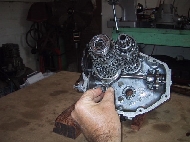
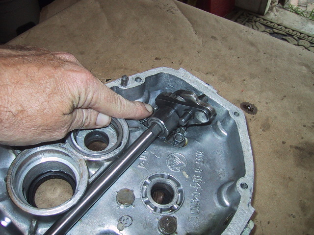
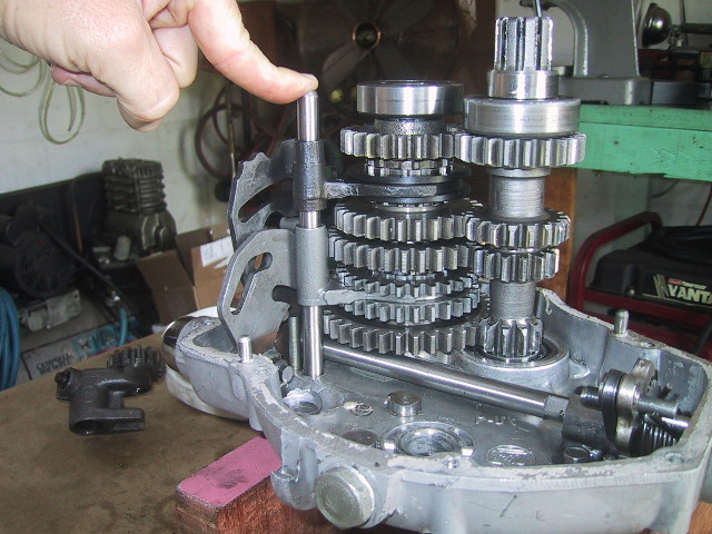
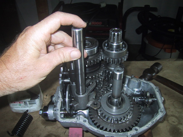
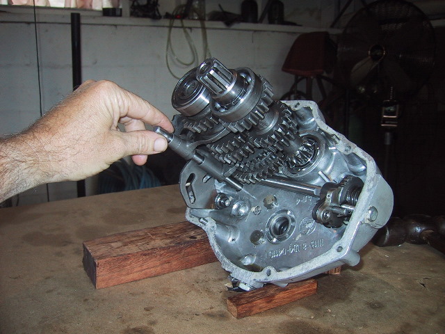 Now grasp the shift fork shaft... |
 ...and pull it free. Use care as the shift forks may fall free. |
 Rotate the 3rd/4th gear shift fork slightly CCW and pull down to remove. |
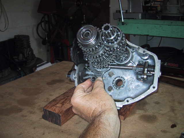 Do the same for the 1st/2nd shift fork. |
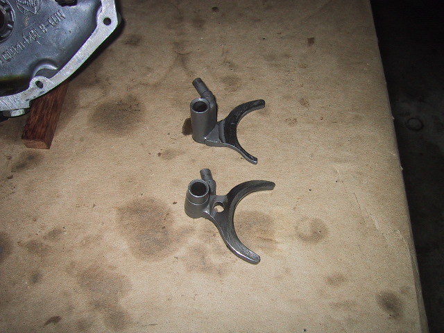 Forks removed. |
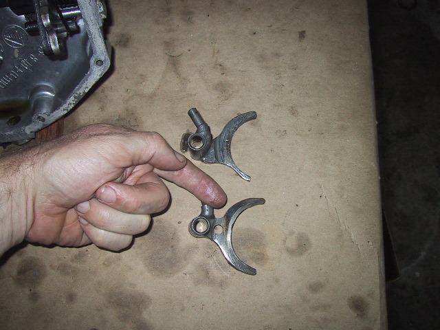 Note the burned and scored area where the 3rd/4th gear fork was rubbing against the 3rd/4th gear shift sleeve. |
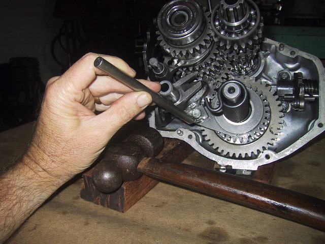
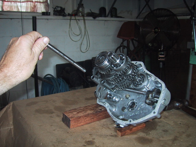
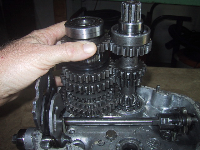
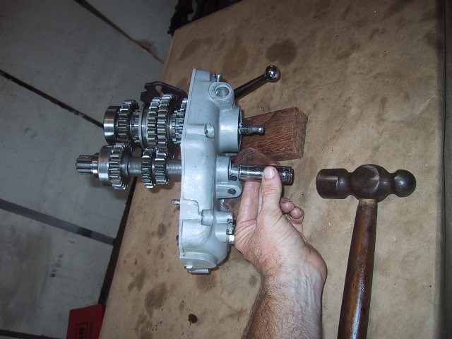 Use a 12mm socket or similar tool to drive the clutch shaft out of its bearing. Make sure the clutch gear teeth are in mesh with the main gear teeth before striking with hammer. |
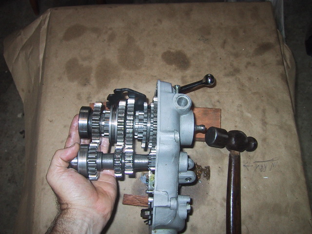 The clutch shaft may not come free due to clearance of the bearing on the end of its shaft. Either way, remove the main shaft and gears by tapping with a hammer on the exposed end of the shaft where the flexible coupling was mounted. |
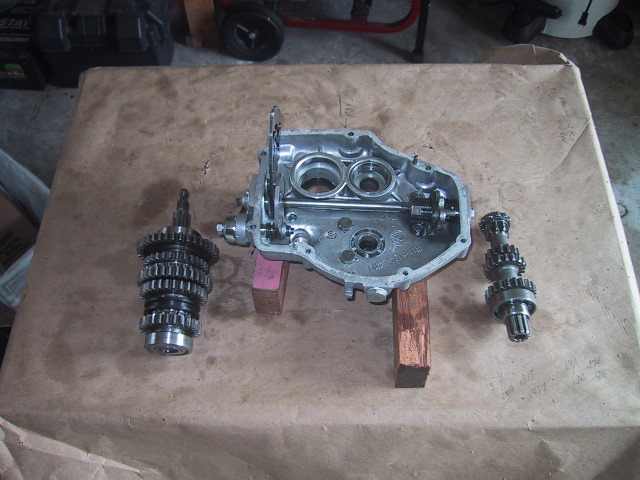
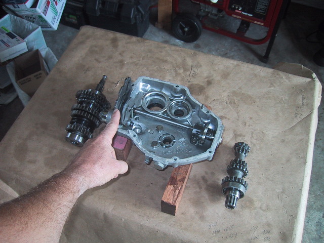
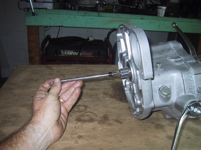
 The main shaft and clutch shaft free of the housing. |
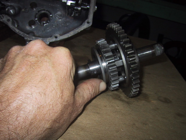
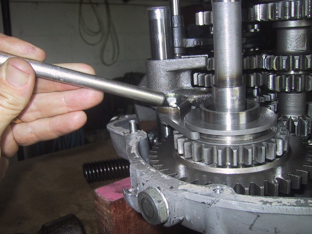
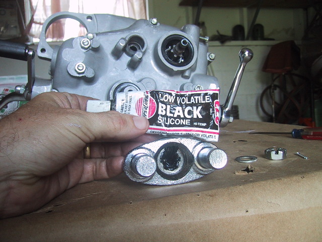
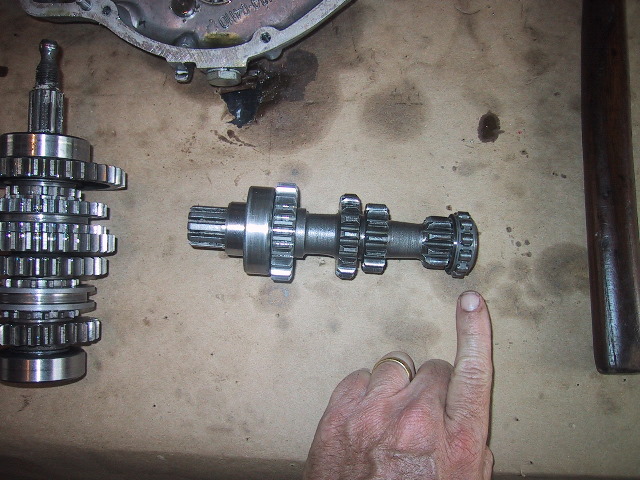 On the aft end of the clutch shaft is the #12204 roller bearing (I am pointing to), The race for this bearing will remain in the case. To remove the race you will need an inside type bearing puller. There are grooves in the case at 12 and 6 o'clock around the race for the puller arms to grab. A #205 bearing is on the front. Either can be removed with a bearing separator. The 4th gear of the clutch shaft (behind #205 bearing on the left) is the only gear that can be replaced on the clutch shaft. It is keyed onto the shaft. |
 Profile view of the main shaft, bearings and gears. Disassembly and description shown below. |
 You may find what appears to be an "odd" seal on the face of the bearing on the aft of the main shaft. This is actually RTV sealant that the factory uses in an attempt to prevent oil from migrating down the splines between the shaft and flexible coupling; and then getting flung off the driveshaft onto your right leg and side of hack. |
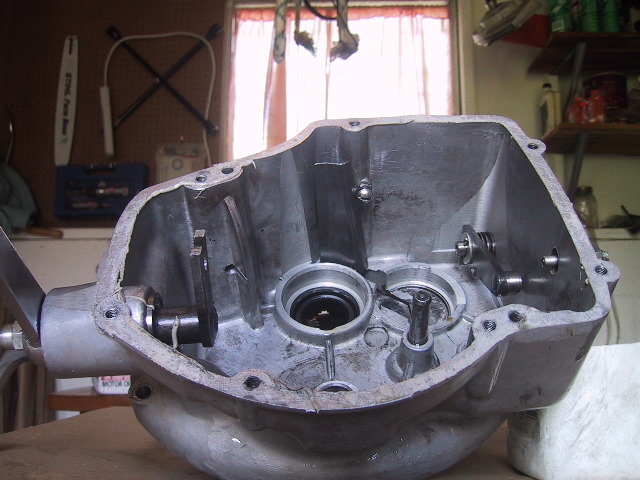
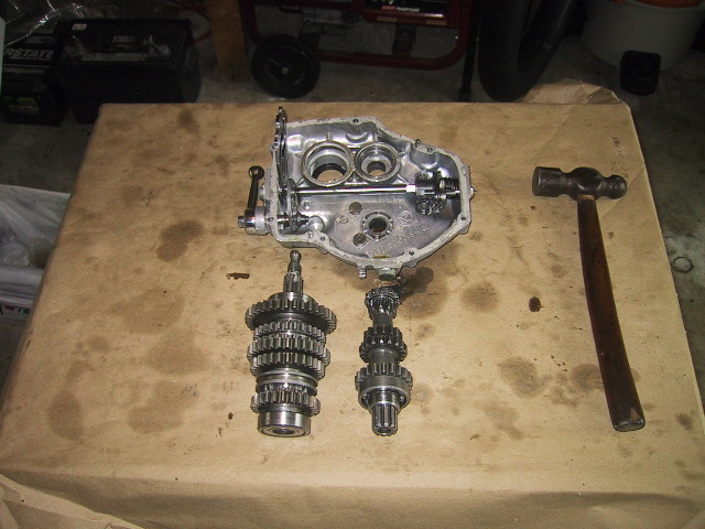
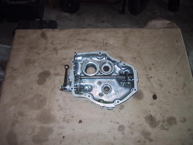 Rear case with all 3 shafts removed. Just to the left of the kick start shaft hole are the 2 pins that the ratchet pawl on the back of the kick start gear locks into. All that remains to be removed is the gear shift mechanism and reverse/neutral shift lever mechanism. Since I do not need to remove these items, I will just describe the procedure for their removal. If you have got this far...the rest is a piece of cake. |
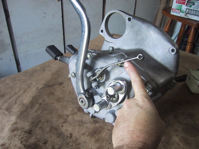
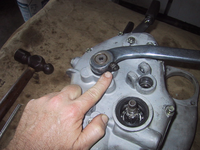
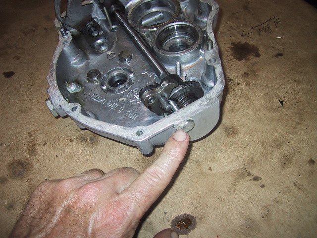
 Here is the reverse shift quadrant... |
 ...this is the stop screw for the reverse quadrant. |
 This is the head of the reverse stop screw and lock nut. |
 When the reverse lever is engaged, the quadrant moves aft to the stop screw... |
 ...you can see a pin from the shift quadrant resting in the guide slot of the reverse quadrant. This is to lock out the shift quadrant while in reverse. This way you can not inadvertently engage a forward gear. |
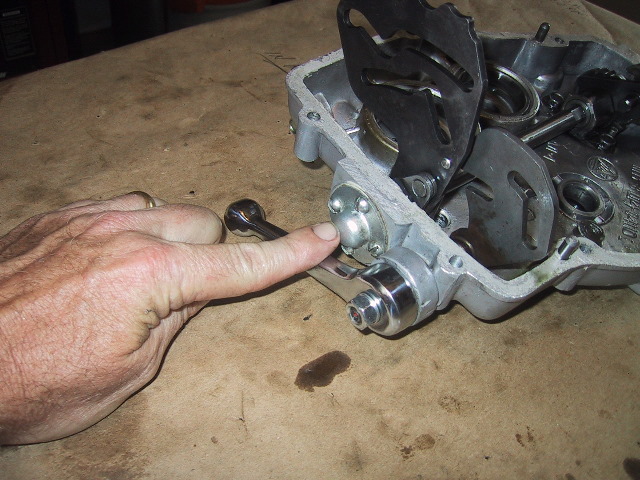
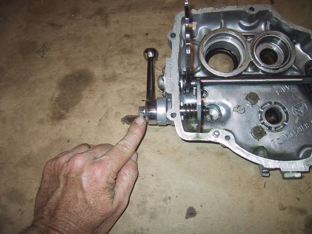
 This is the upper foot shift adjustment screw. It adjusts downshifting. If you are going to remove the foot shift ratchet mechanism and shaft, you will need to remove it along with... |
 ...the up shift adjustment screw. |
 Here are the two adjustment screws and lock nut on the back of the case. |
 Then you will need to cut the safety wire and remove both the 10mm bolts securing the shift ratchet mechanism to the case. |
 The bolt for the shift ratchet mechanism return spring will need to be removed next. |
 Then the 4 screws hold the right side cover of the shift quadrant shaft will need to be removed. Remove the stop pin from the gear shift shaft. The gear shift mechanism can now be removed for repair. |
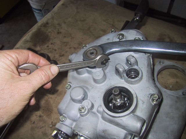
 All that is left is to remove the reverse/neutral lever and quadrant. Use a 13mm wrench to remove the retaining nut of the lever. Mark the position of the lever on the shaft before removing. The lever and shaft end are splined and may require slight prying/pulling to remove the lever. Once the lever is removed, the reverse quadrant and shaft can be pulled free of the case. |
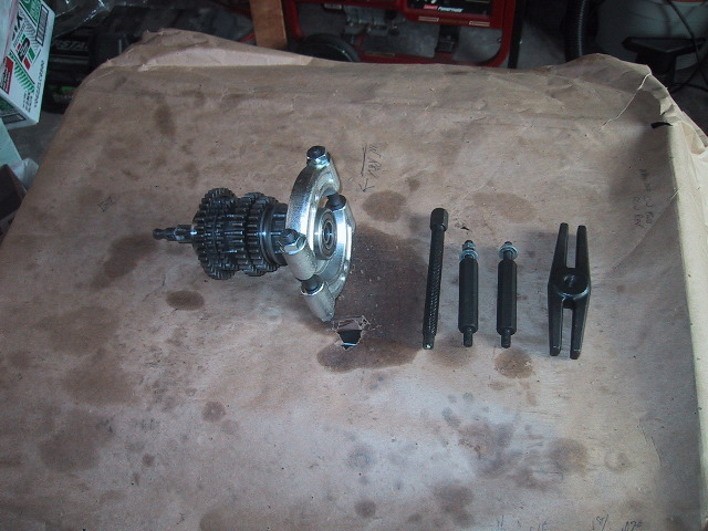 To remove the gears from the main shaft you will need a bearing separator to remove the bearing at each end of the shaft. Place the separator behind the bearing you wish to remove and tighten the separator in place.
|
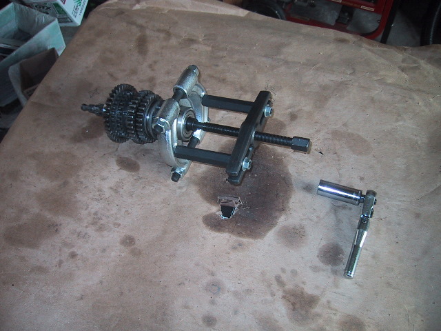 Attach the extension arms and puller screw, use an appropriate wrench to turn the puller screw.... |
 Until the bearing is pulled off. To the left of the bearing is main shaft washer which is under the bearing. !Caution! When the forward bearing (pictured above) is removed; 2nd through 4th gears and sleeves are free to slide off the main shaft onto the floor. When the aft bearing is removed; 1st gear is free to the same. |
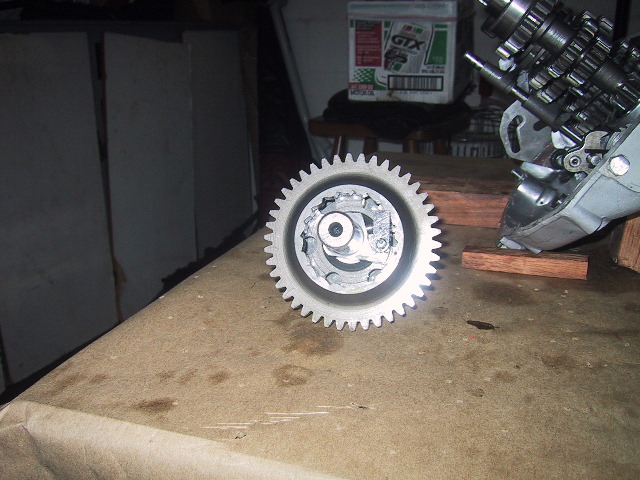
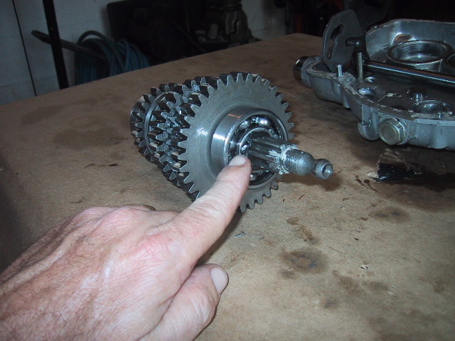
 A view down the shaft looking at the 4th gear riding a top the main shaft sleeve.
|
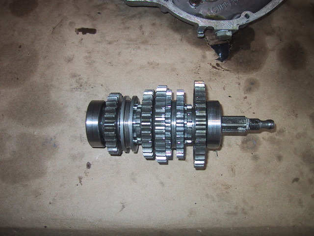
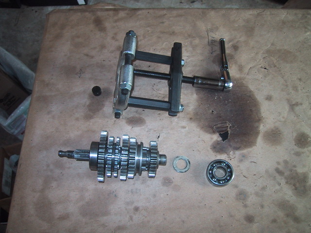
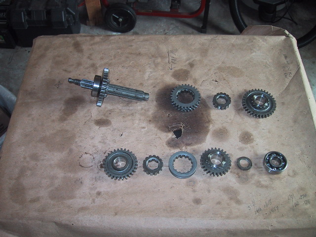 From right to left, bottom to top; Bottom row: #304 bearing, main shaft washer, 4th gear, 3rd/4th shift sleeve, main shaft sleeve, and 3rd gear. Top row: 2nd gear, main shaft sleeve, 1st/2nd shift sleeve (reverse also), main shaft with 1st gear and #304 bearing. |
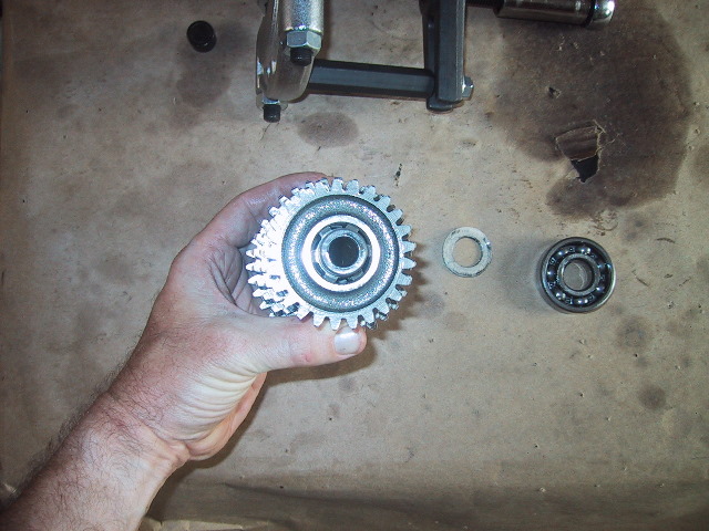
To remove 1st gear,
use bearing separator to pull #304 bearing and gear will slide off. Reassembly for main shaft is reverse of disassembly.
|
5.5(b) Gearbox Assembly
Note: Shift Quadrant and Reverse Quadrant Already Installed
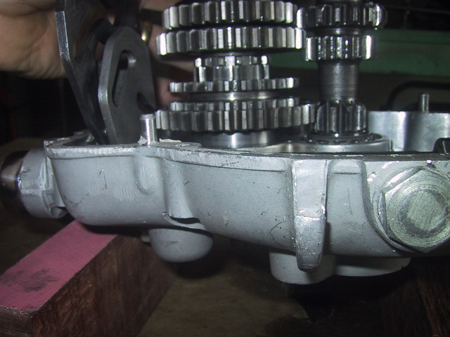
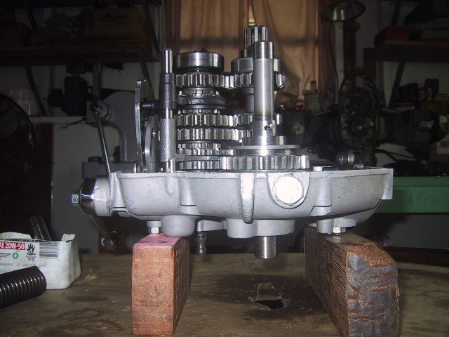
 Place the rear half of the case seam side up on wood blocks to allow room for the ends of the shafts to clear the case underneath. |
 Place the shift quadrant in the neutral position. |
 Press the aft end of the clutch shaft with the #12204 bearing into the race which is already pressed into the case. Hand pressure should suffice. |
 Put the main shaft in place while aligning the mesh of the teeth on the clutch shaft. |
 Seat the bearing of the main shaft as square as possible... |
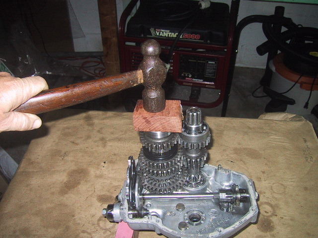 And using a soft hammer or block of wood firmly tap the main shaft home. !Caution! Double check that the gear teeth are meshed between the main and clutch shafts before applying hammer. |
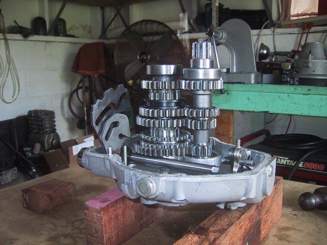 Clutch and main shafts set in housing. |
 Apply motor oil to and install the 1st/2nd and 3rd/4th shift forks onto the appropriate shift sleeves on the main shaft. |
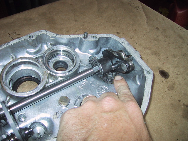
 Apply motor oil to the shift fork shaft and slide it into the shift forks. You may need to slide the shift sleeves up slightly to get the fork pins into the slots of the shift quadrant. |
 Once the fork pins are in the shift quadrant guides, press the shift fork shaft into its hole in the back of the case. |
 Insert the kick start shaft into its case hole... |
 ...while making sure to mesh the gear teeth on the main shaft 1st gear. |
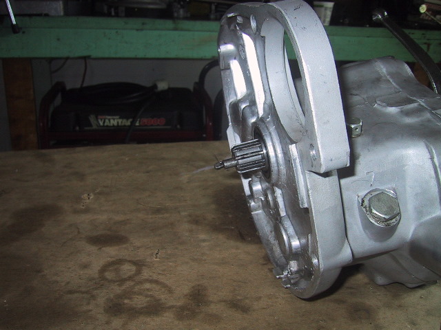
 View of main and kick starter shaft protruding out the back of the gear box case. |
 Slide the idle assembly bracket into place and mesh its gears with the 1st/2nd shift sleeve on the main gear. |
 Slide the idle assembly shaft through the hole in the idle assembly bracket... |
 ...you will need to pull the reverse lever out to compress the spring enough to allow the idle assembly shaft to seat into its hole in the back of the case. |
 Side view of all shafts in place and shift quadrant in neutral. |
 Slide the reverse fork into the sleeve on the reverse gear... |
 ...and swing it up into its position on the idle assembly bracket... |
 ...line up the hole for... |
 ...the retaining bolt and lock washer. |
 Pre bend the lock washer tab 30 degrees or so. |
 Place the lock washer on the idle bracket and use a 12mm socket and ratchet to tighten it down... |
 ...use a tommy bar to bend the lock washer up onto a flat on the bolt head. |
 Slip the kick starter return spring onto the kick starter shaft and turn the spring to engage the shaft pin. |
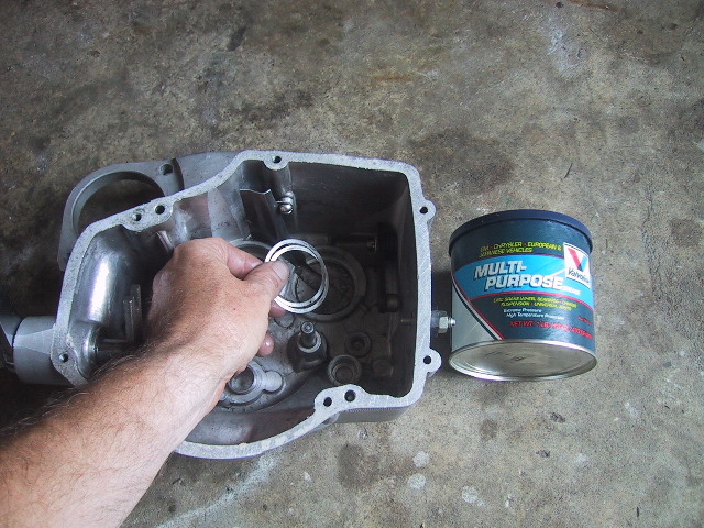 Coat the shims for the front of the main shaft with some grease and place them into the front case. The grease will prevent them from falling out when the front case is inverted for installation. |
 Shims go into this recess for the front main shaft bearing. |
 Use an appropriate sealant like "Yamabond" and coat the seam of the rear case. LocTite can be used in the holes for the alignment pins but is not necessary. |
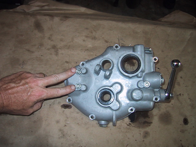
 Rear gear box case and front case ready to be pressed together. |
 At this point you can check your work by manually shifting through the gears. Rotate the clutch shaft CW and move the shift quadrant by hand. When finished, make sure the gear box is in "Neutral". |
 Invert the front cover a carefully place it a top the rear cover so the clutch shaft splines come through the seal. As the halves come together, peek through the crack in the halves and align the gear shift foot pedal shaft fork with the pin on the ratchet crank of the gear shift mechanism. Strike the front case with a hammer to seat the main shaft bearing into the cover.... |
 ...and strike the opposite side to set the front cover flush with the rear cover. |
 Install the 7 gear case cover bolts, put a bit of sealant on the threads to prevent oil leaks. Tighten the bolts using a criss cross pattern. |
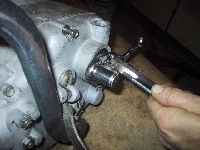
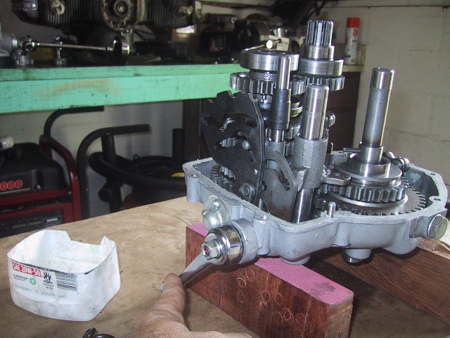
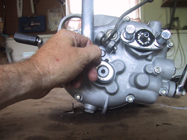
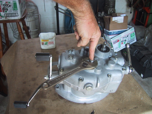 To wind and set the kick starter spring, place an appropriate size wrench (in this case an adjustable wrench) on the end of the kick starter shaft... |
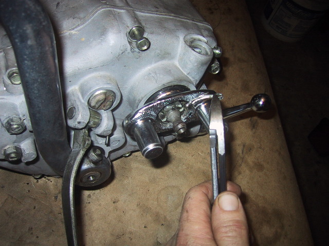
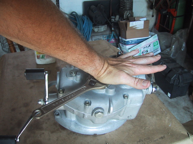 ...press the kick starter shaft down with the palm of your hand while turning the wrench CCW. As the spring catches on the front case, you will feel the pawl fall between the two stop pins on the inside of the back case and the kick starter shaft will pop back up. |
 The end of the kick starter shaft should be oriented like this and spring back into this position when pushed/pulled down with a wrench. |
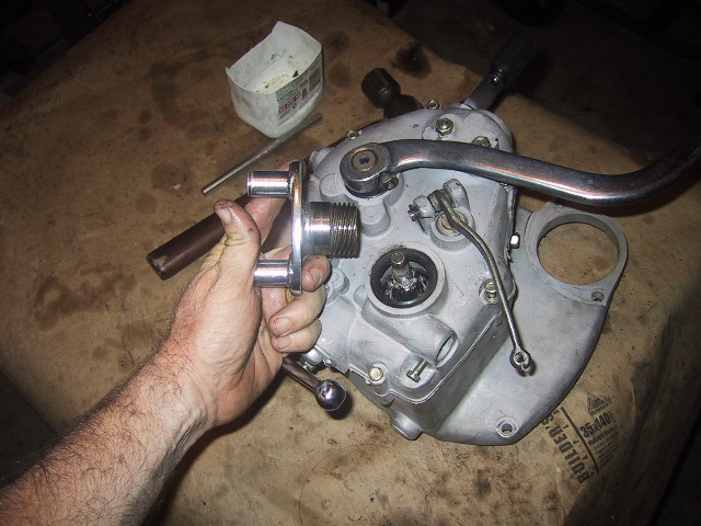
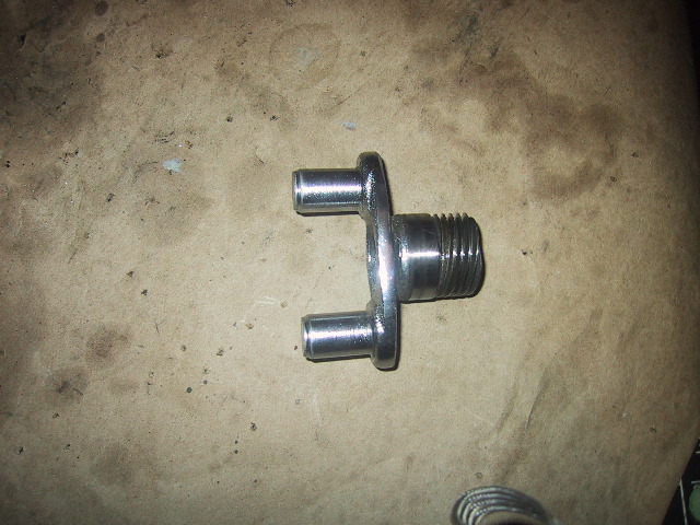
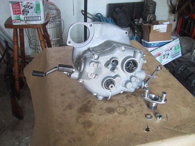 Gather up the parts to install the flexible coupling of the main gear. |
 To help prevent oil from migrating up between the splines of the shaft and coupling, apply a liberal amount of sealant to the coupling splines. |
 Insert the flexible coupling fully on to the main shaft. Wipe any excess sealant from the inside of coupling off. |
 Place the washer on to the end of the main shaft. |
 Spin the 22 mm castellated nut on next, tighten down the nut so the hole for the cotter pin is aligned with one of the slots in the nut. |
 Push the cotter pin into the hole... |
 ...and use a tommy bar and hammer to tap the cotter pin through the shaft. |
 Bend the long arm of the cotter pin back along the flat of the castellated nut to lock it in place. |
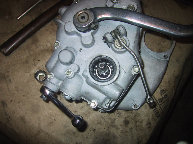
 Next, install the speedometer drive gear, coat it with motor oil before installing. |
 Drop the speedometer gear into the its recess... |
 ...you may need to turn the flexible coupling slightly to mesh the gears and allow the speedometer gear to fully seat. |
 The clutch rod components can now be reinstalled. Give each part a light coat of motor oil before installing. |
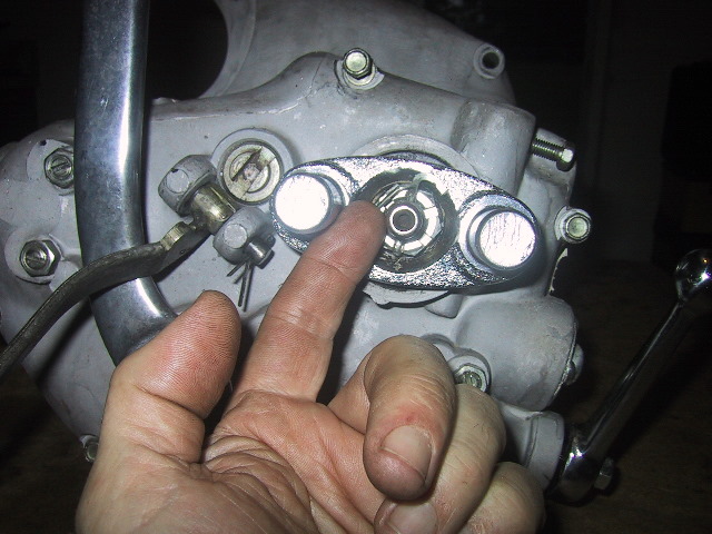
 Insert the clutch release lever... |
 ...followed by the thrust ball bearing plate. Make sure the side with the "largest" ball bearing surface goes in first... |
 ...small bearing surface should face out. |
 Clutch slider with O-ring goes in last. It will take a little thumb pressure to force the slider in. |
 Place the clutch release lever between the bosses and insert the clutch lever pin from the top. |
 Put the cotter pin into the end of the clutch lever pin and bend the big arm back to secure it. |
 Insert the clutch rod seal end first into the clutch shaft... |
 ...it just slides in with nothing holding it in place. |
 Place the kick start lever onto the end of the kick start shaft. |
 Push the kick start wedge pin with the flat facing down into the channel in the kick start lever. |
 Use a tommy bar and hammer to drive the wedge pin in. |
 Put the lock washer on... |
 ...followed by the 13 mm nut. |
 Tighten the nut until it is snug. |
 The gear box is now ready for final gear shift adjustment and test run. |
|
|